Sealing pair of dual-sealing-face valve, dual-sealing-face valve and application of dual-sealing-face valve serving as bypass valve

A valve sealing and sealing surface technology, which is applied in the field of double sealing surface valve sealing pairs, can solve problems such as the decline in the working capacity of the steam turbine, the increase in the exhaust temperature of the steam turbine, and the overheating of the tube wall temperature of the low-temperature reheater of the boiler, etc. Flexible and reliable, improved sealing performance, and reduced switching force

Pending Publication Date: 2019-09-24
哈尔滨松林电站设备有限公司
View PDF0 Cites 1 Cited by
  • Summary
  • Abstract
  • Description
  • Claims
  • Application Information

AI Technical Summary

Problems solved by technology

However, at present, the bypass valves of many power plants have the defect of internal leakage. The internal leakage of the bypass valve will cause part of the steam to bypass the corresponding cylinder of the steam turbine, which will reduce the working ability of the steam turbine and reduce the operating economy; at the same time, it may also cause the boiler Low temperature reheater tube wall temperature overheating; possible increase in turbine exhaust temperature

Method used


Image

  • Sealing pair of dual-sealing-face valve, dual-sealing-face valve and application of dual-sealing-face valve serving as bypass valve
  • Sealing pair of dual-sealing-face valve, dual-sealing-face valve and application of dual-sealing-face valve serving as bypass valve
  • Sealing pair of dual-sealing-face valve, dual-sealing-face valve and application of dual-sealing-face valve serving as bypass valve

Examples


Embodiment Construction

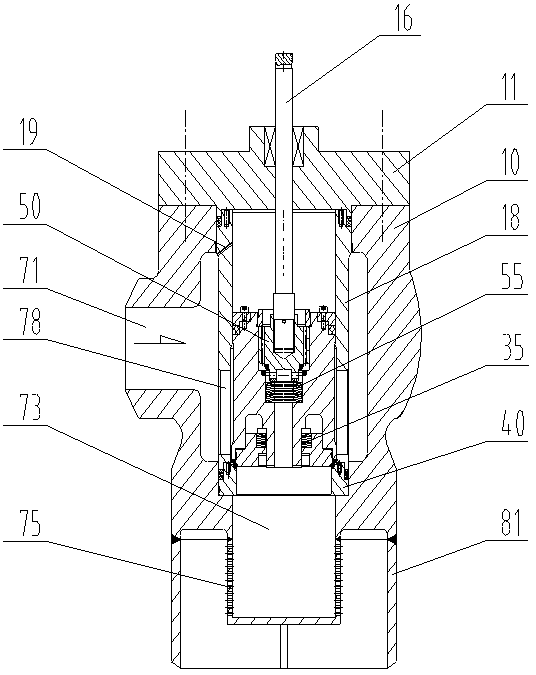
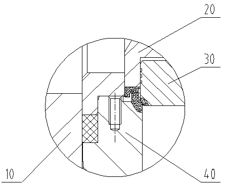
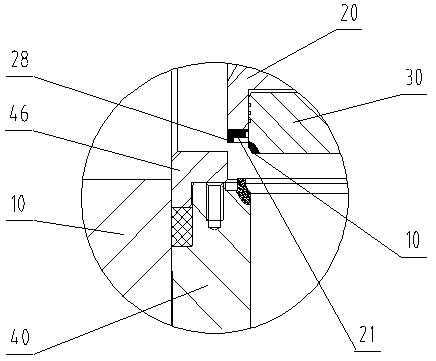
[0023] see Figure 1-5 , the present invention provides a double sealing surface valve sealing pair, which includes a valve seat 40 and a valve core, the valve seat is provided with a first sealing surface 41 and a second sealing surface 42, the first sealing surface of the valve seat Located on its upper end surface, it can be an annular plane, or an appropriate shape such as an annular arc surface. The second sealing surface of the valve seat is located on the upper part of the inner surface of the valve seat, preferably an annular conical surface, also It can be a suitable shape such as an annular protrusion. The valve core includes a first valve flap 20 and a second valve flap 30. The first valve flap is provided with a sealing surface 21, and the sealing surface of the first valve flap is located at Its lower end surface adopts a structure that matches the first sealing surface of the valve seat, and forms a first valve sealing pair with the first surface cover of the val...


PUM


Abstract

The invention relates to a sealing pair of a dual-sealing-face valve, the dual-sealing-face valve and application of the dual-sealing-face valve serving as a bypass valve. According to the sealing pair of the dual-sealing-face valve, a valve seat is provided with a first sealing face and a second sealing face; a valve element comprises a first valve clack and a second valve clack; the first valve clack and the second valve clack are provided with sealing faces; the second valve clack is located in a columnar groove in the lower end face of the first valve clack and is in sliding with the side wall of the columnar groove; and a thrust spring used for pushing the second valve clack downwards is arranged between the first valve clack and the second valve clack. The dual-sealing-face valve comprises a valve body and a main sealing pair. The sealing pair of the dual-sealing-face valve is adopted as the main sealing pair. An auxiliary valve sealing pair and a corresponding auxiliary valve medium channel can be arranged on the first valve clack. The above valve can be used as the bypass valve, especially the bypass valve of a bypass system of a steam turbine. The sealing performance of the valve can be improved, and bypass leaking of the valve or the steam turbine can be avoided or relieved.

Description

technical field [0001] The invention relates to a double sealing surface valve sealing pair, a double sealing surface valve adopting the valve sealing pair and the application of the double sealing surface valve as a bypass valve, especially the application in a steam turbine bypass system. Background technique [0002] At present, the steam turbine bypass system supporting the thermal power generation unit plays an important role in the start-up, shutdown and operation of the unit. It is used to increase the steam pressure and steam temperature of the boiler during the start-up process of the unit, and is used to recover The working fluid is used to prevent boiler overpressure during unit accident tripping and load shedding. However, at present, the bypass valves of many power plants have the defect of internal leakage. The internal leakage of the bypass valve will cause part of the steam to bypass the corresponding cylinder of the steam turbine, which will reduce the worki...

Claims


Application Information

Patent Timeline
IPC IPC(8): F16K1/46F16K1/42F16K1/36F16K1/32F16K1/52
CPCF16K1/465F16K1/42F16K1/36F16K1/32F16K1/52
Inventor 许文波于艳敏李京哲
Owner 哈尔滨松林电站设备有限公司
Why Eureka
Try Eureka