Cable connector box

An optical cable splice box and housing technology, applied in the directions of light guides, optics, optical components, etc., can solve the problems of poor sealing effect, non-reusable rubber blocks and rubber strips, and inability to apply to optical cables of various diameters. The effect of combining and improving the sealing performance

Inactive Publication Date: 2011-10-19
TYCO ELECTRONICS (SHANGHAI) CO LTD
View PDF5 Cites 6 Cited by
  • Summary
  • Abstract
  • Description
  • Claims
  • Application Information

AI Technical Summary

Problems solved by technology

[0003] However, the sealing effect between the rubber block and the rubber strip is not good, and the existing rubber block and rubber strip cannot be reused and cannot be applied to optical cables of various diameters. In view of

Method used


Image

  • Cable connector box
  • Cable connector box
  • Cable connector box

Examples


Embodiment Construction

[0021] The technical solutions of the present invention will be further specifically described below through the embodiments and in conjunction with the accompanying drawings. In the specification, the same or similar reference numerals designate the same or similar components. The following description of the embodiments of the present invention with reference to the accompanying drawings is intended to explain the general inventive concept of the present invention, but should not be construed as a limitation of the present invention.

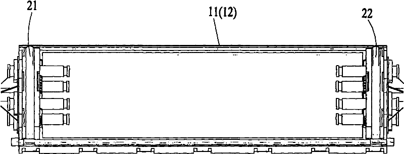
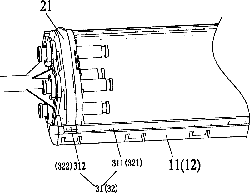
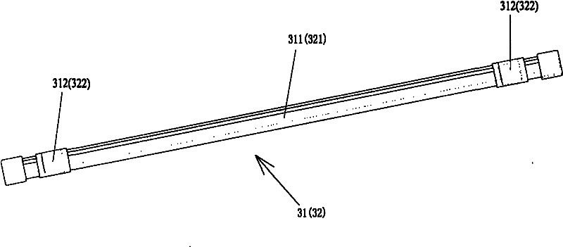
[0022] Figure 1 to Figure 4 An optical cable splice closure according to an exemplary embodiment of the present invention is shown.

[0023] figure 1 A schematic diagram showing an optical cable splice closure according to an exemplary embodiment of the present invention; figure 2 show figure 1 A partially enlarged schematic diagram of the optical cable splice box in .

[0024] Such as figure 1 and figure 2 As shown, the optical cabl...


PUM


Abstract

The invention discloses a cable connector box which comprises a shell, a pair of end sealing blocks and a pair of edge sealing strips, wherein the shell comprises an upper shell body and a lower shell body which are coordinated with each other; the pair of end sealing blocks are used to seal the two ends of the shell, the peripheries of the end sealing blocks are injected gels; the pair of edge sealing strips are respectively used to seal the two edges of the upper shell body and the lower shell body, wherein the two edges are coordinated with each other and extend along the length direction of the cable connector box, each edge sealing strip comprises a rubber strip and an injection sealing layer which is injected on the rubber strip; the injection sealing layer is sealed fit with the gels on the peripheries of the end sealing blocks, and the injection sealing layer is made of gel. Compared with the prior art, in each embodiment of the invention, the edge sealing strip is sealed fit with the gel layer injected on the peripheries of the end sealing blocks, therefore, the sealing performance between the edge sealing strip and the end sealing blocks is improved.

Description

technical field [0001] The invention relates to an optical cable joint closure, in particular to an optical cable joint closure with reliable sealing performance. Background technique [0002] In the prior art, the housing of the optical cable splice closure generally includes an upper housing and a lower housing that cooperate with each other. For the existing casing, two rubber blocks are generally used to seal the two end openings of the casing, and two rubber strips are used to seal the two edges extending along the length direction of the optical cable splice box that cooperate with each other on the upper and lower casings. When the upper and lower shells are put together, the upper and lower shells press the rubber block at the end and the rubber strip at the edge, and at the same time the rubber block and the rubber strip are also in contact with each other and pressed together, thus The sealing of the outer shell of the entire optical cable splice closure is realiz...

Claims


Application Information

Patent Timeline
IPC IPC(8): G02B6/44
CPCG02B6/4447
Inventor 张陆军
Owner TYCO ELECTRONICS (SHANGHAI) CO LTD
Why Eureka
Try Eureka