Magnetofluid sealing structure

A ferrofluid seal and permanent magnet technology, which is applied to engine seals, engine components, mechanical equipment, etc., can solve the problems of unfavorable sealing structure lightweight, difficult to achieve vacuum sealing, and seal failure, so as to facilitate equipment lightweight, Effect of improving pressure resistance and enhancing sealing performance

Active Publication Date: 2018-04-24
GUANGXI UNIVERSITY OF TECHNOLOGY
View PDF8 Cites 6 Cited by
  • Summary
  • Abstract
  • Description
  • Claims
  • Application Information

AI Technical Summary

Problems solved by technology

[0006] 1. On the outer surface of the rotating shaft, the area where the magnetic fluid is sealed is the optical axis section. Once the magnetic fluid leaks, it will cause complete leakage and seal failure
[0007] 2. If a single-stage seal is used, the magnetic supply capacity is weak, the magnetic sealing performance is poor, and i

Method used


Image

  • Magnetofluid sealing structure

Examples


Example Embodiment

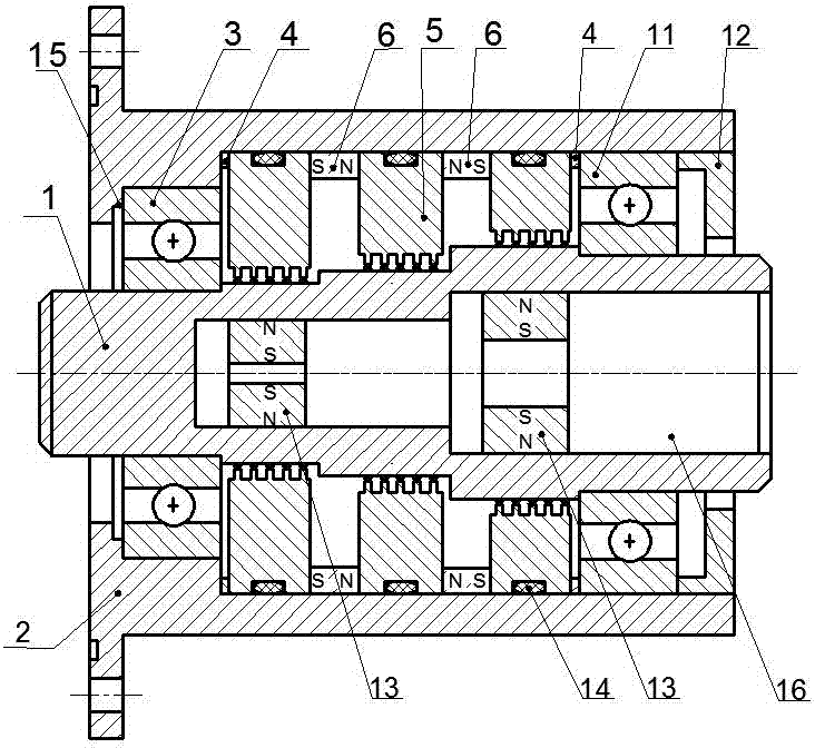
[0033] Such as figure 1 As shown, a magnetic fluid sealing structure includes a hollow housing 2 and a rotating shaft 1 arranged in an inner cavity of the housing 2, and the rotating shaft 1 and the housing 2 are assembled and connected by a bearing.

[0034] There are multiple steps on the outer surface of the rotating shaft 1, and the height difference between two adjacent steps is 1 to 5 mm.

[0035] Two second permanent magnets 6 are provided in the radial direction between the outer surface of the rotating shaft 1 and the inner wall of the housing 2, and the second permanent magnets 6 are axially magnetized permanent magnet rings. Each second permanent magnet 6 is provided with pole shoes 5 on both sides, and each pole shoe 5 is arranged directly opposite to one of the first steps. There are three pole shoes 5, and two second permanent magnets 6 are arranged between two adjacent pole shoes 5. The number of steps provided on the outer surface of the rotating shaft 1 is the sa...


PUM


Abstract

The invention discloses a magnetofluid sealing structure. The magnetofluid sealing structure comprises a hollow shell and a rotating shaft; the rotating shaft and the shell are connected through a bearing in an assembled mode, multistage of steps are arranged on the outer surface of the rotating shaft, and at least one second permanent magnet is arranged in the radial direction between the outer surface of the rotating shaft and the inner wall of the shell; pole shoes are arranged on the two sides of each second permanent magnet, and each pole shoe is arranged to directly face one of the steps; gaps exist between the pole shoes and the outer surface of the rotating shaft, and magnetofluid is injected to the gaps; the rotating shaft is provided with a cavity, first permanent magnets are mounted in the cavity, and each first permanent magnet is correspondingly arranged in a magnetic circuit formed by the corresponding second permanent magnet and the pole shoes on the two sides of the corresponding second permanent magnet; and the field directions of the first permanent magnets are the same as that of the magnetic circuits where the first permanent magnets are located. According to the magnetofluid sealing structure, by additionally provided with the first permanent magnets, sealing performance of the magnetofluid is improved, the anti-pressure capability of magnetofluid sealing is increased, and the rotating shaft is designed by adopting a stepped shaft form, so that loss of the magnetofluid during sealing failure is reduced.

Description

technical field [0001] The invention specifically relates to a magnetic fluid sealing structure. Background technique [0002] The magnetic fluid seal has the advantages of no solid friction between the seals, long service life of the seals, and zero leakage. Among them, one of the applications is for the sealing of rotating shafts, such as vacuum sealing (ion implanters, x-ray diffractometers, etc.), gas sealing (x-ray tubes, etc.), liquid sealing (deep water pumps, ship screw propeller shafts, etc.) ) and dust-proof seals (textile machinery, computer hard drives, etc.). [0003] One of the methods to improve the pressure resistance of magnetic fluid seals in large gaps is to improve the structure of magnetic fluid seals, such as the sealing devices described in Chinese patents CN206320304U and CN203348559U. Although the sealing performance of the two sealing devices described in the above patent documents has been greatly improved compared with ordinary magnetic fluids, ...

Claims


Application Information

Patent Timeline
IPC IPC(8): F16J15/43
CPCF16J15/43
Inventor 杨小龙陈帆孙彭郝付祥何美丽郭星
Owner GUANGXI UNIVERSITY OF TECHNOLOGY
Why Eureka
Try Eureka