
Control valve

A control valve and valve seat technology, which is applied to fuel injection valves, engine components, and machines/engines driven by fluid pressure. Effect

Active Publication Date: 2016-04-13
ROBERT BOSCH GMBH
View PDF6 Cites 0 Cited by
  • Summary
  • Abstract
  • Description
  • Claims
  • Application Information

AI Technical Summary

Problems solved by technology

However, a higher magnetic force is required to open the valve, which in turn has a negative effect on the switching times of the control valve

Method used


Image

  • Control valve
  • Control valve
  • Control valve

Examples


Embodiment Construction

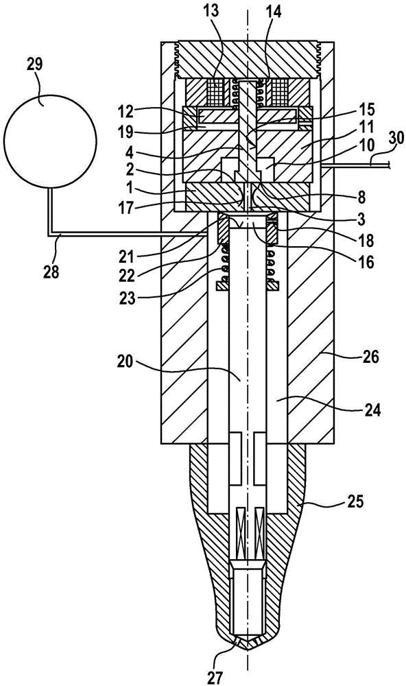
[0033] figure 1 The fuel injector shown in has a nozzle body 25 and a holding body 26 which are axially clamped by means of a clamping nut, not shown. The nozzle body 25 and the holding body 26 are penetrated by a high-pressure bore 24 in which the nozzle needle 20 is accommodated in a reciprocating linear motion for releasing or closing the injection opening 27 . The high-pressure opening 24 is connected via a supply line 28 to a high-pressure accumulator 29 , via which fuel under high pressure is delivered to the high-pressure opening 24 .

[0034] The high-pressure bore 24 is delimited in the axial direction by the valve block 1 of the control valve for controlling the reciprocating linear movement of the nozzle needle 20 , which is inserted into the holding body 26 . The valve block 1 seals off the high-pressure opening 24 from the low-pressure chamber 10 which is formed within the valve body 11 of the control valve. Through the hole 15 of the valve body 11 and through t...


PUM


Abstract

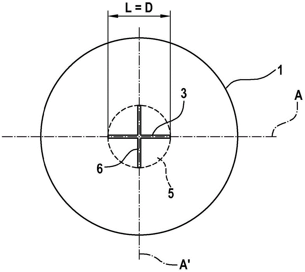
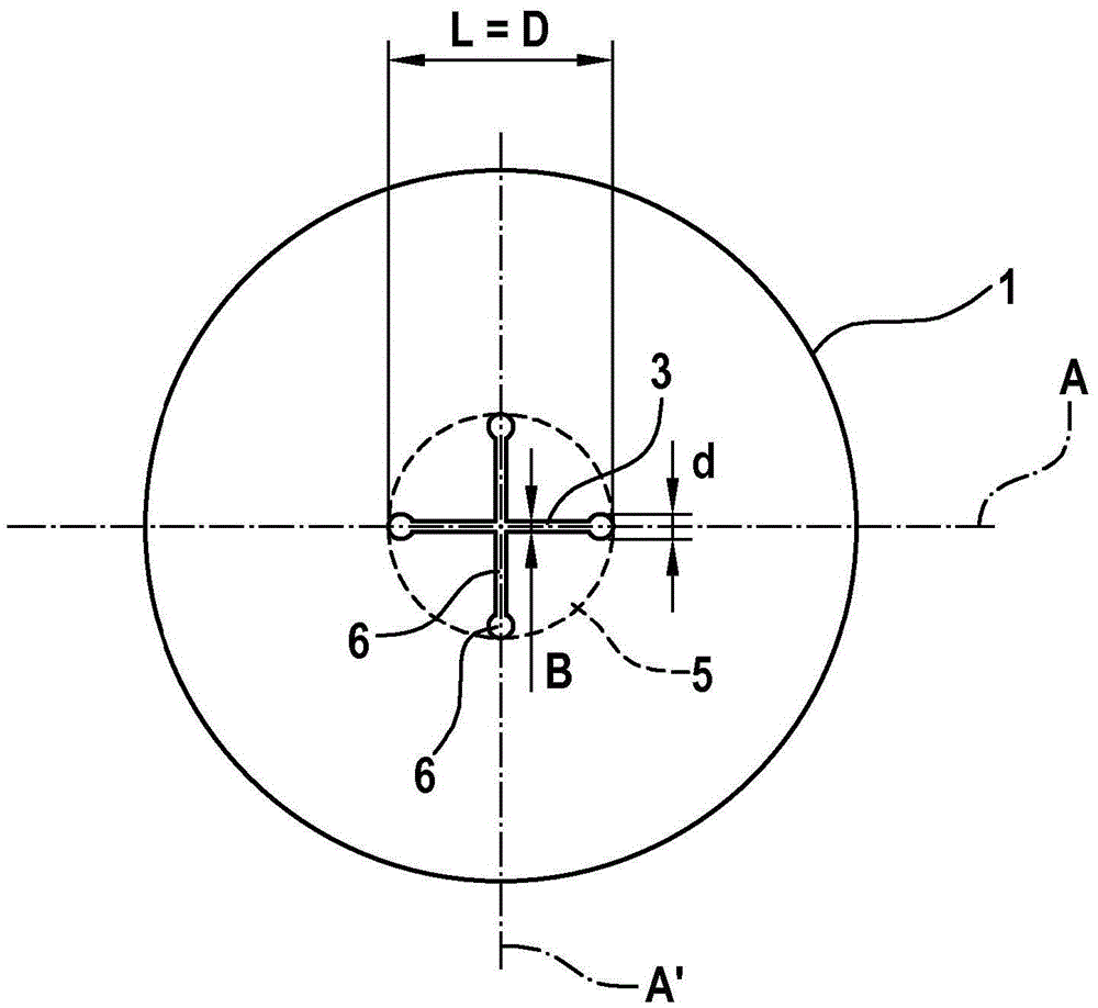
The invention relates to a control valve for a fuel injector, in particular a common-rail fuel injector, comprising a valve piece (1) having an outflow opening (3) which is formed inside a valve seat (2) formed as a flat seat, and a reciprocating valve-closing element (4) which interacts in a seal-forming fashion with the valve seat (2). According to the invention, the outflow opening (3) is embodied in a slit shape and has a length (L) which is greater than a width (B), wherein the length (L) corresponds essentially to a diameter (D) or a radius (R) of a circular surface (5), within which the outflow opening (3) and at least one further outflow opening (6, 6') which is connected to the outflow opening (3) and / or separated from the outflow opening (3) are arranged. The invention also relates to a fuel injector having a control valve of said type.

Description

technical field [0001] The invention relates to a control valve for a fuel injector, in particular a common rail fuel injector, having the features of the preamble of claim 1 . The invention also relates to a fuel injector with such a control valve. Background technique [0002] Control valves of the type mentioned above are commonly used in fuel injectors having a nozzle needle with reciprocating linear motion for releasing and closing at least one injection orifice. The control valve is used here to control the reciprocating linear motion of the nozzle needle. If the control valve is open, the control chamber is unloaded, so that the control pressure acting on the nozzle needle in the control chamber in the closing direction decreases and the nozzle needle opens. The actuation of the control valve is usually carried out by means of actuators, for example magnetic actuators or piezoelectric actuators. [0003] Laid-open document DE 10 2006 049 050 A1 discloses by way of ...

Claims


Application Information

Patent Timeline
IPC IPC(8): F02M47/02F02M63/00
CPCF02M47/027F02M63/0017F02M63/0033F02M63/0077F02M2547/003F02M2547/008
Inventor D·库恩克
Owner ROBERT BOSCH GMBH
Learn More