Expansion tank

Active Publication Date: 2021-09-30
HONDA MOTOR CO LTD
View PDF0 Cites 1 Cited by
  • Summary
  • Abstract
  • Description
  • Claims
  • Application Information

AI Technical Summary

Benefits of technology

The present invention is an expansion tank that can prevent the formation of vortex flows and air bubbles in the coolant liquid. It does this by using a barrier wall, which suppresses the generation of vortex flows near the coolant liquid outlet. This results in a smooth flow of coolant liquid from the tank. Overall, this invention improves the efficiency and performance of coolant systems.

Problems solved by technology

However, in the conventional reserve tank or expansion tank, it is difficult to sufficiently suppress the vortex flow of the coolant liquid generated above the coolant liquid outlet, and there is a limit to suppressing the inflow of bubbles into the coolant liquid circulation passage.

Method used


Image

  • Expansion tank
  • Expansion tank
  • Expansion tank

Examples


Embodiment Construction

)

[0022]In the following, one embodiment of an expansion tank according to the present invention will be described with reference to FIGS. 1 to 4.

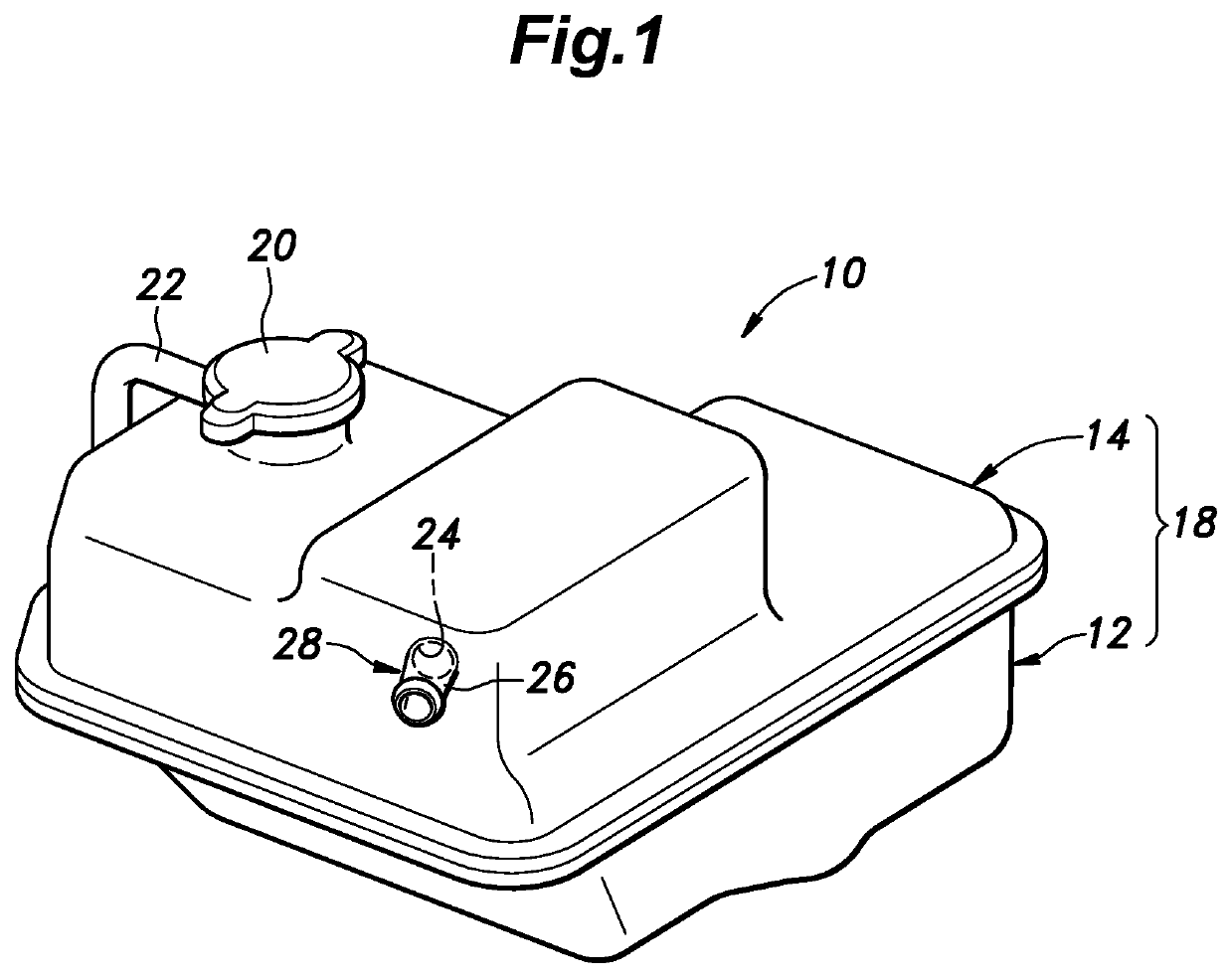
[0023]As shown in FIG. 1, an expansion tank 10 of the present embodiment includes a tank main body 18 constituted of a lower tank member 12 and an upper tank member 14 that are airtightly joined to each other and are each made of resin. The tank main body 18 defines a storage chamber 16 (see FIG. 2) storing a coolant liquid therein. On the upper tank member 14, a lid cap 20 equipped with a relief valve and an air vent tube 22 is mounted.

[0024]The upper tank member 14 is provided with a coolant liquid inlet portion 28 including an inlet opening 24 that is open to a later-described inlet chamber 34 and a coolant liquid inlet tube 26 communicating with the inlet opening 24 and extending to outside of the tank main body 18.

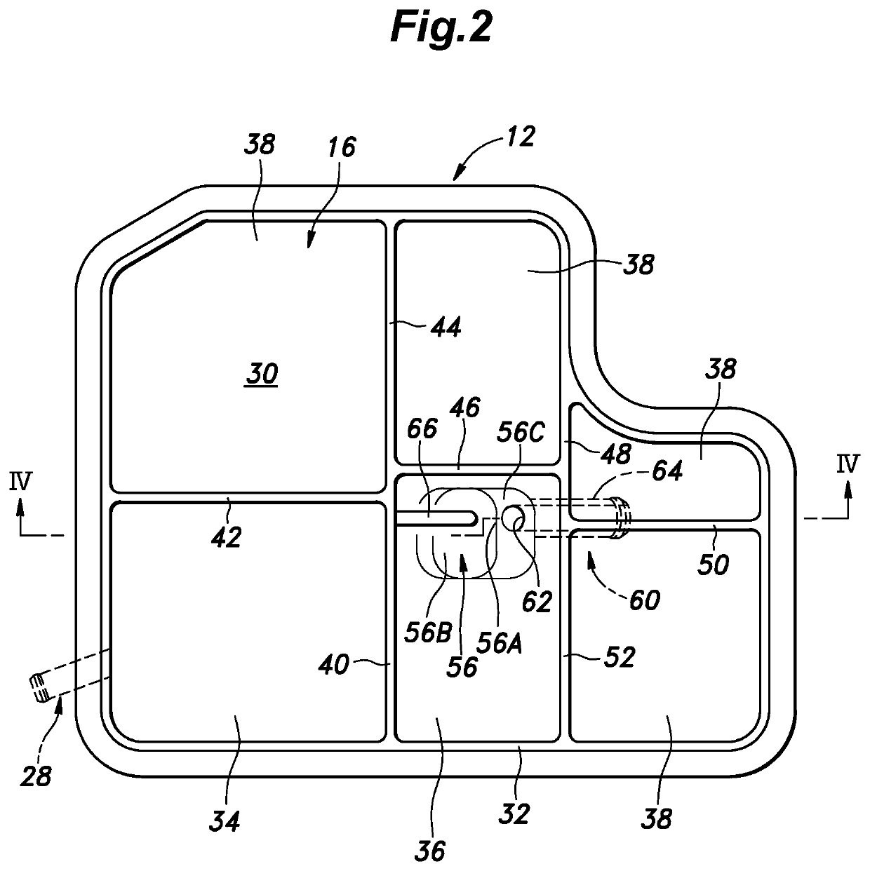
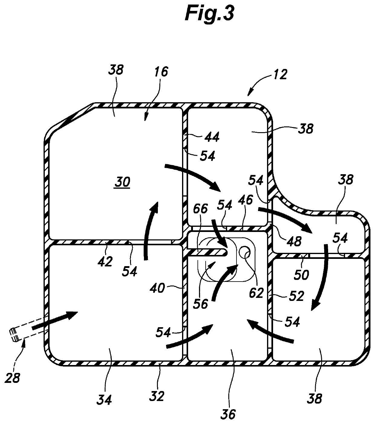
[0025]As shown in FIG. 2 and FIG. 3, the lower tank member 12 has a bottom wall 30 and a side wall 32 which extends along a...


PUM


Abstract

An expansion tank, includes: a tank main body defining a storage chamber storing a coolant liquid therein; multiple partition walls provided in the tank main body to divide the storage chamber into multiple division chambers including an inlet chamber and an outlet chamber, the partition walls being formed with communication holes for bringing adjacent ones of the division chambers into communication with each other; a coolant liquid inlet portion that is provided on the tank main body and is open to the inlet chamber; a coolant liquid outlet portion that has an outlet opening in a depression formed in a bottom of the tank main body and is open to the outlet chamber; and a barrier wall extending from a side wall of the tank main body or one of the partition walls into the depression.

Description

TECHNICAL FIELD[0001]The present invention relates to an expansion tank, and more specifically to an expansion tank used in a cooling system of an internal combustion engine.BACKGROUND ART[0002]An expansion tank used in a cooling system of an internal combustion engine is connected to a coolant liquid circulation passage including a radiator or the like, and is configured to absorb the volume fluctuation of the coolant liquid owing to temperature changes by admitting and expelling the coolant liquid into and out of the expansion tank as required. A known expansion tank of this kind includes a tank main body defining a storage chamber for storing the coolant liquid therein, multiple partition walls provided in the tank main body to divide the storage chamber into multiple division chambers including an inlet chamber and an outlet chamber, the partition walls being formed with communication holes for bringing adjacent ones of the division chambers into communication with each other, a...

Claims


Application Information

Patent Timeline
IPC IPC(8): F01P11/02
CPCF01P11/029F01P11/00F01P11/04F01P11/02
Inventor KOMATSU, SHUJIHOTTA, NAOKIKOIDE, KEIJIROSHIMOYAMA, SHINJIFUKUZAWA, ICHIROFUKADA, YUSUKE
Owner HONDA MOTOR CO LTD
Why Eureka
Try Eureka