Liquid heating device

Inactive Publication Date: 2005-08-16
PAN HUANG CHUAN +1
View PDF4 Cites 0 Cited by
  • Summary
  • Abstract
  • Description
  • Claims
  • Application Information

AI Technical Summary

Benefits of technology

[0008]1. It includes a pump for pumping liquid into a helical heating tube, which has its two ends connected to two output terminals of an a control system, When the control system is started, the helical heating tube is powered to product high heat to heat up at once the liquid therein to a proper temperature, or boil up or vaporize it

Problems solved by technology

If liquid is to be heated up in 10-20 minutes, the heating tube can be small to use small amount of electricity, but it takes time, not convenient to use.
The conventional liquid heating device described above uses the electric heating tube 10 for ind

Method used


Image

  • Liquid heating device
  • Liquid heating device
  • Liquid heating device

Examples


Example

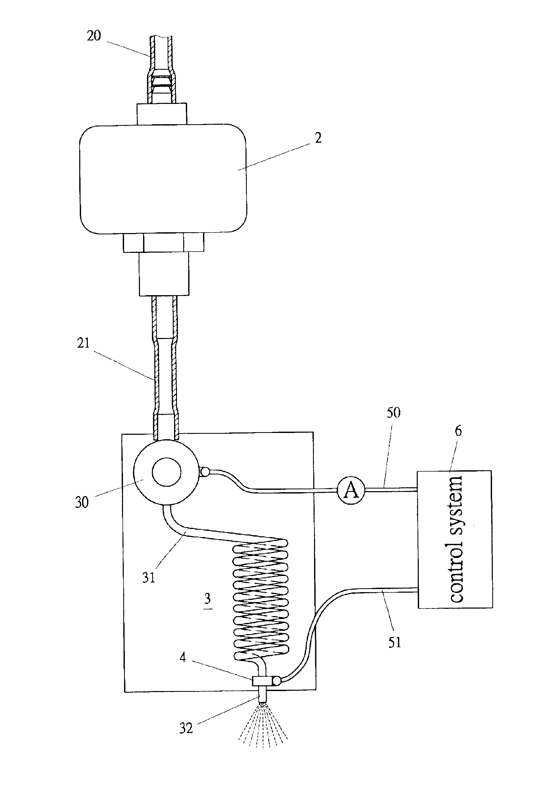
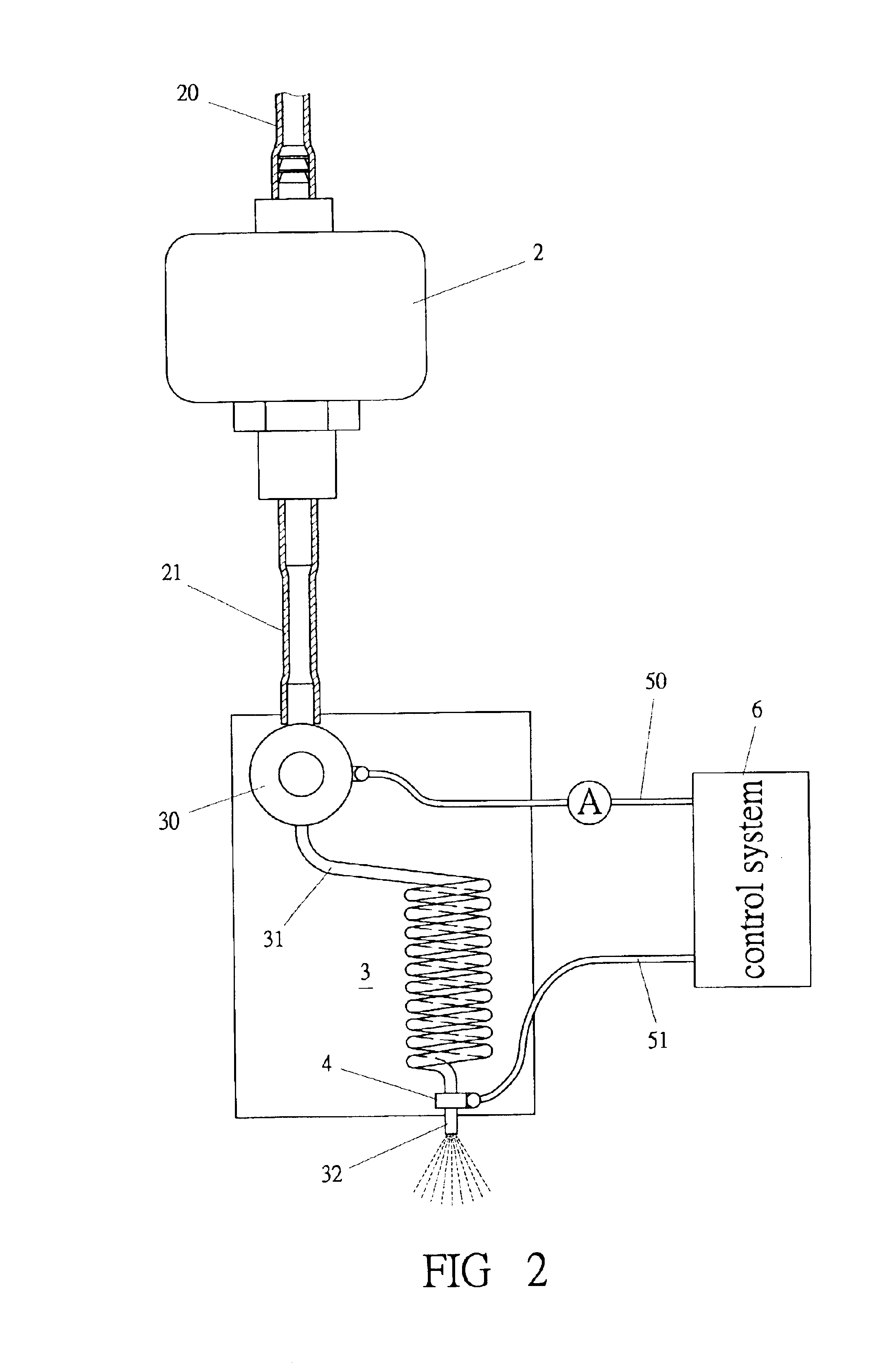
[0014]A preferred embodiment of a liquid heating device in the present invention, as shown in FIG. 2, includes a pump 2, a heating tube 3 and a control system 6 as main components combined together.

[0015]The pump 2 has an inlet tube 20 fixed on a side of the pump 2 for pumping in liquid in a liquid store tank (not shown), and an outlet tube 21 connected to the heating tube 3.

[0016]The heating tube 3 is shaped helical, having an inlet end 31 connected with a connect tube 30, and an outlet end 32 passing through a tube clamp 4 consisting of two leading wires 40 as shown in FIGS. 3 and 4. Then two electric wires 50,51 are respectively connected to the connect tube 30 and the tube clamp 4.

[0017]The control system 6 is used to control electric power to be supplied to the two electric wires 50,51 to electrify and heat up the heating tube 3 to directly heat up liquid therein quickly to high temperature so as to vaporizing liquid at the outlet end 32. In other words, instant electrifying ca...


PUM


Abstract

A liquid heating device includes a pump for pumping liquid, and a helical heating tube receiving liquid sent by the pump. The two ends of the helical heating tube are connected with two terminals of electric power, and when a control system is started, the helical heating tube is heated up to produce high heat to heat up the liquid therein to a proper temperature, to boil it up or change it into vapor for practical use.

Description

FIELD OF THE INVENTION[0001]This invention is continued-in-part of Ser. No. 10 / 157,471 filed on May 23, 2002 U.S. Pat. No. 6,705,252 capable to heat up liquid speedily to a proper temperature or to boil it or change it into vapor, and applicable to a drink water dispenser, a heater or any equipment for heating liquid.BACKGROUND OF THE INVENTION[0002]A common conventional liquid heating device generally includes a cast block 1 made of zinc-aluminum alloy and an electric heating tube 10 and a water conveying tube 11 both contained in the cast block 1. Then the cast block 1 is heated up by the electric heating tube 10, and then the water conveying tube 11 is heated up by the heat of the cast block 1 so that liquid flowing in the water conveying tube 11 is also heated up to become airy vapor. The time required in vaporizing may be 2-3 minutes at least or more than ten minutes at latest depending on the capacity of the electric heating tube 10. If liquid in the tube 11 is to be vaporized...

Claims


Application Information

Patent Timeline
IPC IPC(8): F22B1/00F22B1/28
CPCF22B1/282
Inventor PAN, HUANG CHUANCHEN-LUNG, HUANG
Owner PAN HUANG CHUAN
Why Eureka
Try Eureka