Electromagnetic valve

Inactive Publication Date: 2012-01-26
ADVICS CO LTD +1
View PDF13 Cites 0 Cited by
  • Summary
  • Abstract
  • Description
  • Claims
  • Application Information

AI Technical Summary

Benefits of technology

[0009]In consideration of the foregoing, it is an object of the invention to provide an electromagnetic valve in which it is possible to reduce the amount of fluctuation in pressure differential relative to fluctuation in flow rate.
[0011]As mentioned above, the electromagnetic valve is so structured that the conical portion is provided at the tip of the valve body. With this configuration, when fluid hits the conical portion of the valve body, the fluid is bounced back at substantially the same angle at which it hit the conical surface of the conical portion. However, the direction of movement of the bounced fluid is not inclined so much from the direction in which the fluid is to be caused to flow as compared with, for example, the valve bodies that do not have a conical portion and whose tip is all spherical. Therefore, the flow resistance is made lower than spherical surfaces and the fluid can smoothly flow. In addition, the generatrices of the conical surface of the conical portion are matched with the tangent lines to the spherical surface; and the boundary area between the spherical surface and the conical surface is continuous without a step and the fluid is rectified by these surfaces when it flows. For this reason, it is possible to reduce the amount of fluctuation in pressure differential relative to fluctuation in the flow rate of the fluid.
[0012]The tip of this conical portion can be formed in a pointed shape. However, the tip of the conical portion may be configured as a spherical surface as according to a second aspect of the invention; or the tip of the conical portion may be configured as a flat surface as according to a third aspect of the invention. In case of these shapes, the flow resistance is slightly increased as compared with cases where the tip of the conical portion is in a pointed shape. However, the same effect as according to the first aspect can be obtained.

Problems solved by technology

However, these conventional electromagnetic valves involve a problem.
When fluid flows in the gap between the valve seat and the valve body through a flow path connecting to the valve seat provided in a seat, the fluid that hit the tip of the valve body configured as a spherical surface cannot smoothly flow.
Also in normally closed electromagnetic valves, the tip of their valve body is spherical and the same problem as above arises.

Method used


Image

  • Electromagnetic valve
  • Electromagnetic valve
  • Electromagnetic valve

Examples


first embodiment

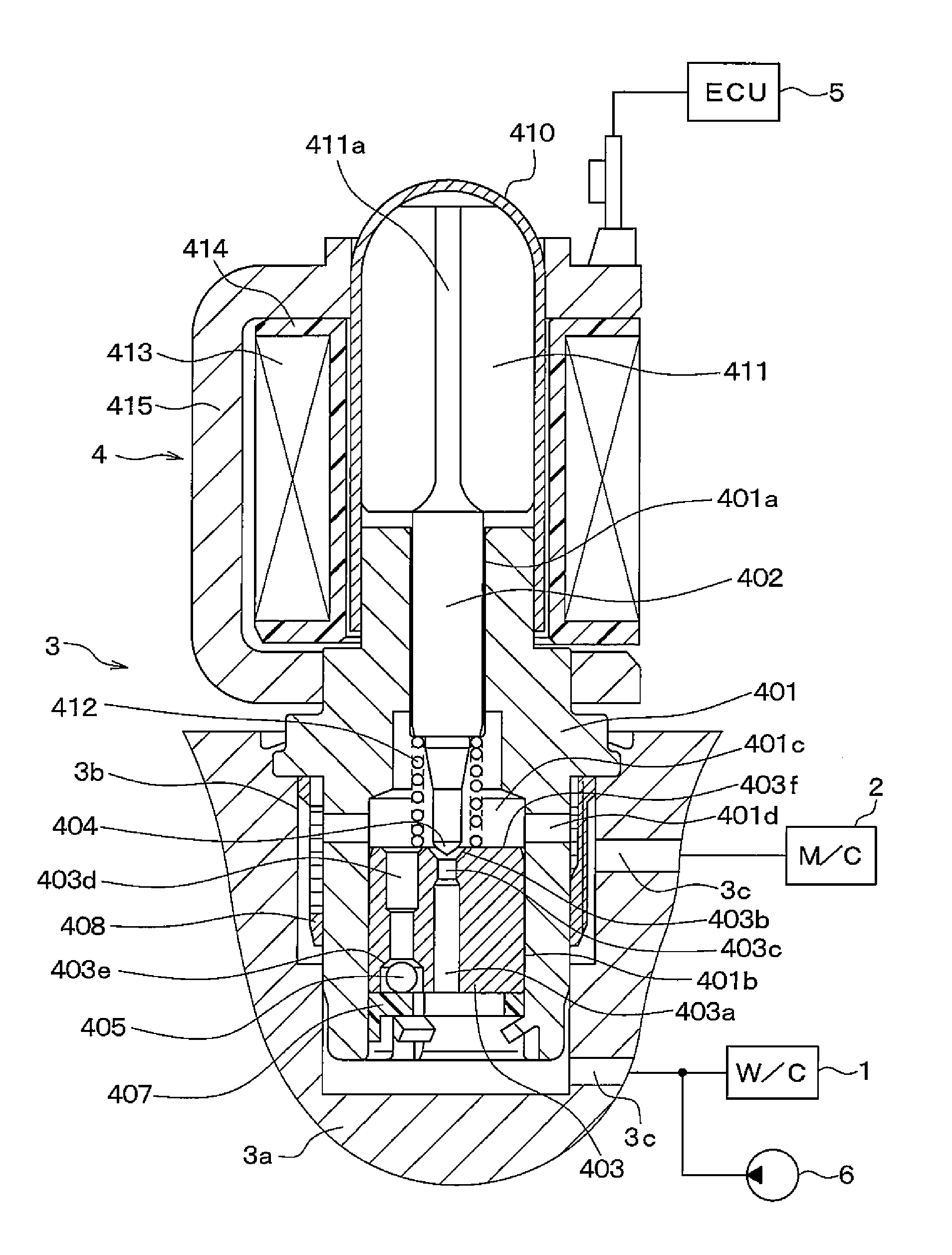
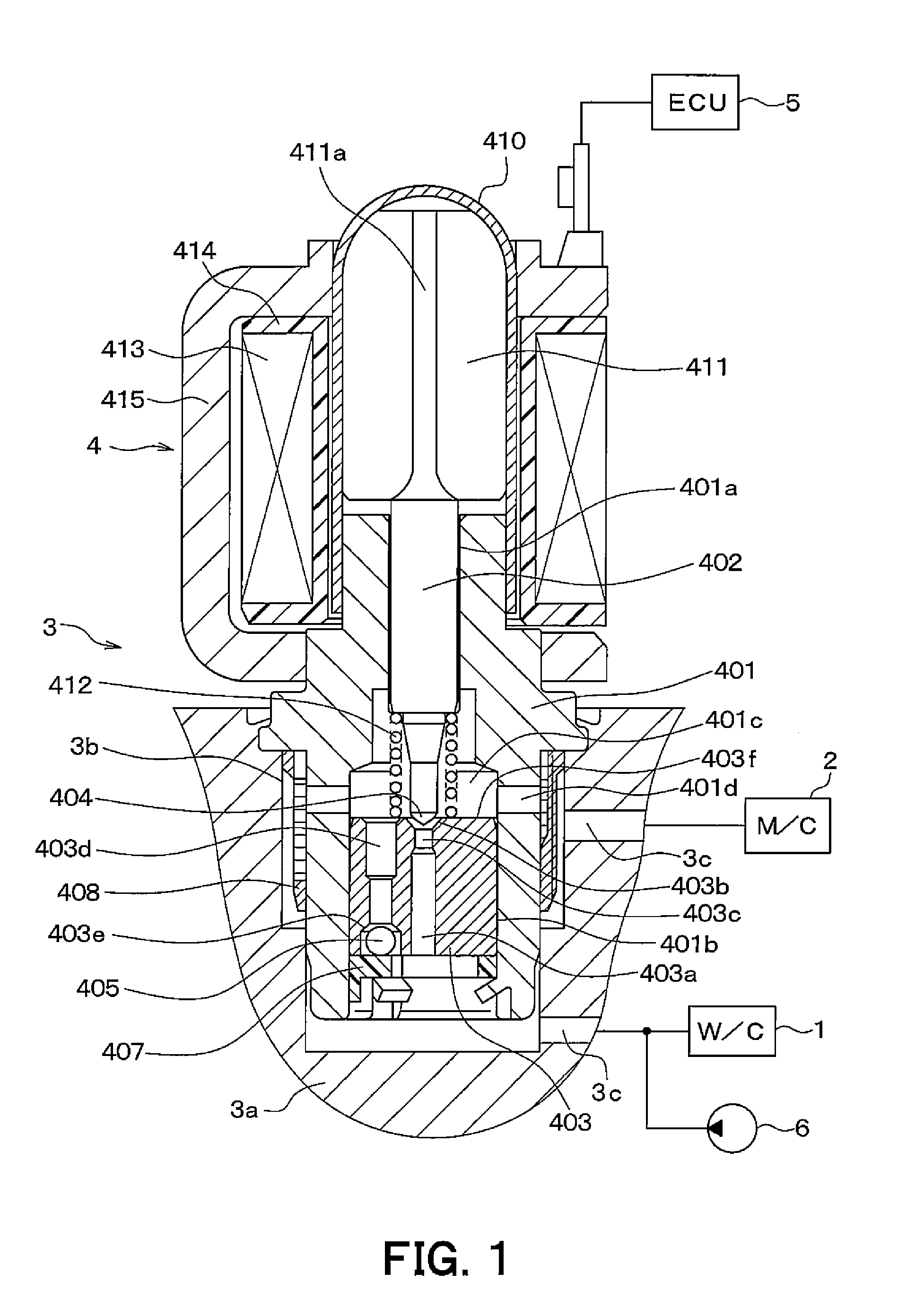
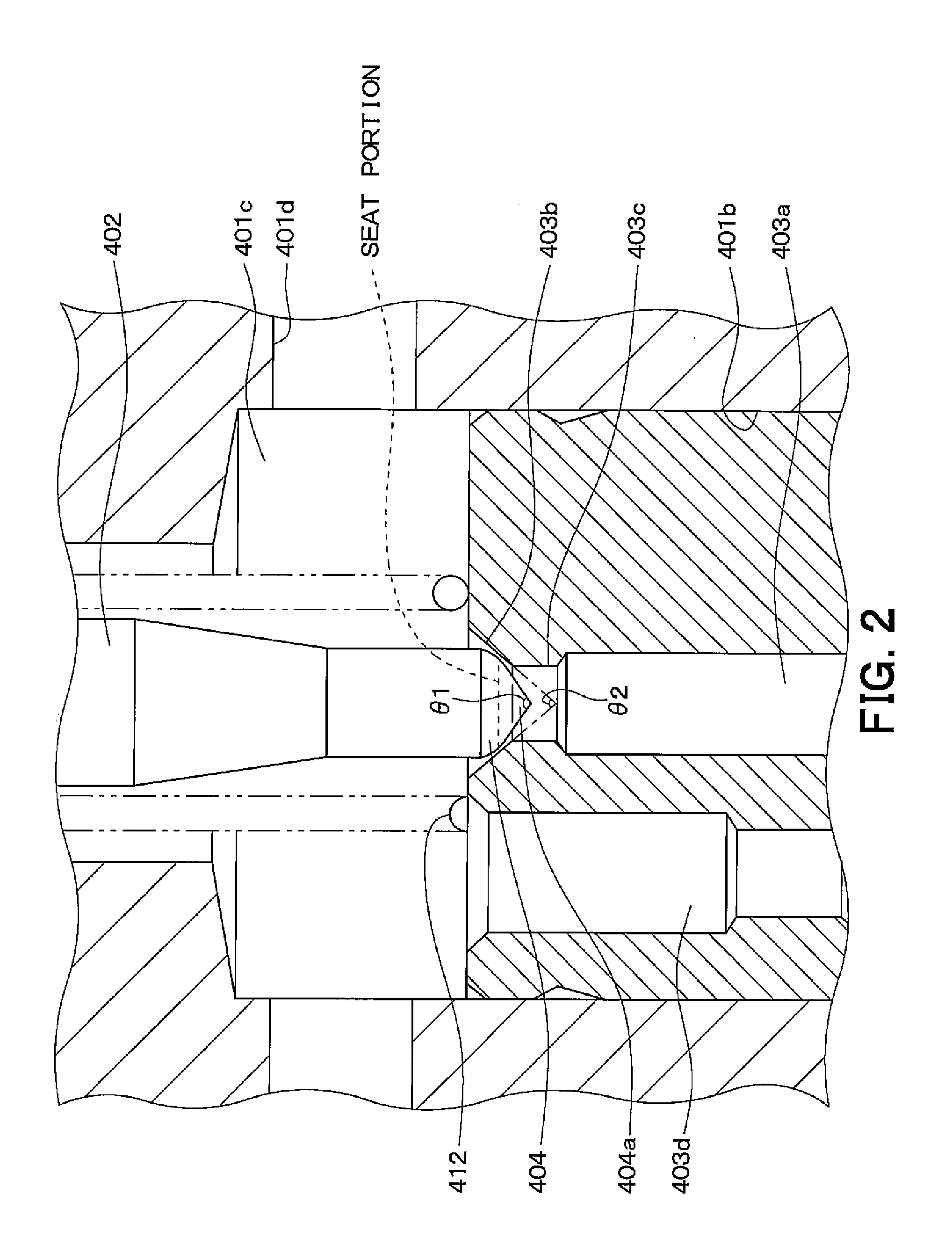
[0019]Description will be given to the first embodiment of the invention. FIG. 1 is a front sectional view of a normally open electromagnetic valve in the first embodiment of the invention as is assembled to the housing of an actuator; and FIG. 2 is a front sectional view of a substantial part of the electromagnetic valve in FIG. 1.

[0020]As illustrated in FIG. 1, a hydraulic pressure control actuator 3 that controls brake fluid pressure is placed between the master cylinder (hereafter, abbreviated as M / C) 2 and a wheel cylinder (hereafter, abbreviated as W / C) 1 of a vehicle. The hydraulic pressure control actuator 3 includes a housing 3a of aluminum alloy and the following are formed in this housing 3a: a stepped columnar recessed portion 3b into which an electromagnetic valve 4 is inserted; and a flow path 3c for circulating brake fluid between the M / C 2 and the W / C 1.

[0021]The electromagnetic valve 4 includes a stepped cylindrical guide 401 formed of magnetic material. One end of ...

second embodiment

[0050]Description will be given to a second embodiment of the invention. This embodiment is obtained by modifying the shape of the tip of the main valve body 404 in the first embodiment. The other respects are the same as those in the first embodiment and description will be given only to the difference.

[0051]FIG. 4 is an enlarged sectional view of the vicinity of the main valve body 404 of the electromagnetic valve 4 in this embodiment. As illustrated in this drawing, the conical portion 404a is formed at the tip of the main valve body 404 as in the first embodiment. Further, the apex of the conical portion 404a is rounded to form a spherical surface 404b. This spherical surface 404b is smaller in radius than the spherical surface 404b of the seat portion at the tip of the main valve body 404 brought into or out of contact with the main valve seat 403b.

[0052]In the electromagnetic valve 4 with this configuration, the spherical surface 404b is formed at the tip of the conical porti...

third embodiment

[0054]Description will be given to a third embodiment of the invention. This embodiment is also obtained by modifying the shape of the tip of the main valve body 404 in the first embodiment. The other respects are the same as those in the first embodiment and description will be given only to the difference.

[0055]FIG. 5 is an enlarged sectional view of the vicinity of the main valve body 404 of the electromagnetic valve 4 in this embodiment. As illustrated in this drawing, the conical portion 404a is formed at the tip of the main valve body 404 as in the first embodiment. Further, the apex of the conical portion 404a is eliminated to form a flat surface 404c. That is, the conical portion 404a is formed in a circular truncated cone shape.

[0056]In the electromagnetic valve 4 with this configuration, the flat surface 404c is formed at the tip of the conical portion 404a. Therefore, when a pressure differential is produced between the upstream and the downstream of the electromagnetic v...


PUM


Abstract

A conical portion is provided at the tip of a main valve body. When brake fluid hits the conical portion of the main valve body, the brake fluid is bounced back at substantially the same angle at which it hits the conical surface of the conical portion. However, the movement direction of the bounced brake fluid is not largely inclined from the direction that the brake fluid is to be caused to flow. Therefore, the flow resistance is reduced. Further, generatrices of the conical portion agree with tangent lines to the spherical surface and the boundary area between the spherical surface and the conical surface is continuous without a step. Therefore, the brake fluid is rectified by these surfaces when it flows. It is possible to reduce the amount of fluctuation in pressure differential relative to fluctuation in the flow rate of brake fluid.

Description

CROSS REFERENCE TO RELATED APPLICATION[0001]This application is based upon and claims the benefit of Japanese Patent Application No. 2010-162786 filed on Jul. 20, 2010, the content of which are incorporated herein by reference.FIELD OF THE INVENTION[0002]The present invention relates to an electromagnetic valve in which a different pressure state can be established by shifting the position of a valve body by energization and which is favorably applicable to, for example, an actuator of ABS (Antilock Brake System) for avoiding the lock tendency of wheels.DESCRIPTION OF RELATED ART[0003]An electromagnetic valve applied to an actuator of ABS has been conventionally proposed in Patent Document 1 (JP-A-2002-347597). The electromagnetic valve described in Patent Document 1 is a normally open on-off controlled electromagnetic valve that operates as described below. A plunger sucked when a coil is energized is slidably housed in a closed-end cylindrical sleeve. A valve member that is actuat...

Claims


Application Information

Patent Timeline
IPC IPC(8): F16K31/02
CPCF16K31/0658B60T8/363
Inventor ISHIKAWA, MOTOKAZUYABUKI, YUUJI
Owner ADVICS CO LTD
Why Eureka
Try Eureka