Suction tube of stratified scavenging engine

Active Publication Date: 2018-01-25
YAMABIKO CORP
View PDF3 Cites 0 Cited by
  • Summary
  • Abstract
  • Description
  • Claims
  • Application Information

AI Technical Summary

Benefits of technology

The present invention provides a suction tube for a stratified scavenging engine that improves flexibility in designing the air-fuel mixture passage and air passage, allows for continuous and smooth changes in shape, reduces the number of components, and facilitates attachment and assembly while also reducing production cost. The suction tube consists of a cylindrical exterior member and an interior member that are individually formed and assembled together, making it easy to realize smooth air flow and optimal engine performance. The interior member is attached to the cylindrical exterior member using the elastic deformation of the exterior member or the interior member being made of rubber, further reducing the number of components and simplifying the attachment process.

Problems solved by technology

Therefore, the shapes and layouts of the air-fuel mixture passage and the air passage are significantly restricted, and it is thus quite difficult to allow for continuous and smooth changes in the shapes of the cross sections of the passages from the inlet side toward the outlet side, specifically, changes, for example, in the shapes of the cross sections of the air-fuel mixture passage from a semi-circular shape to a rectangular shape and the air passage from a semi-circular shape to a horizontally elongated rectangular shape.
Without continuous and smooth changes in the cross sections of the air-fuel mixture passage and the air passage, the air-fuel mixture and air do not smoothly flow and as a result, required engine performance cannot be obtained.
However, such a configuration disclosed in Patent Document 1 requires more components and more time for attaching and assembling of the components, and thus is costly.

Method used


Image

  • Suction tube of stratified scavenging engine
  • Suction tube of stratified scavenging engine
  • Suction tube of stratified scavenging engine

Examples


first embodiment

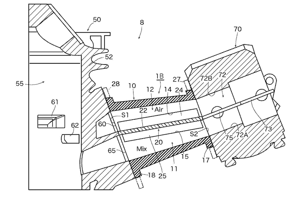
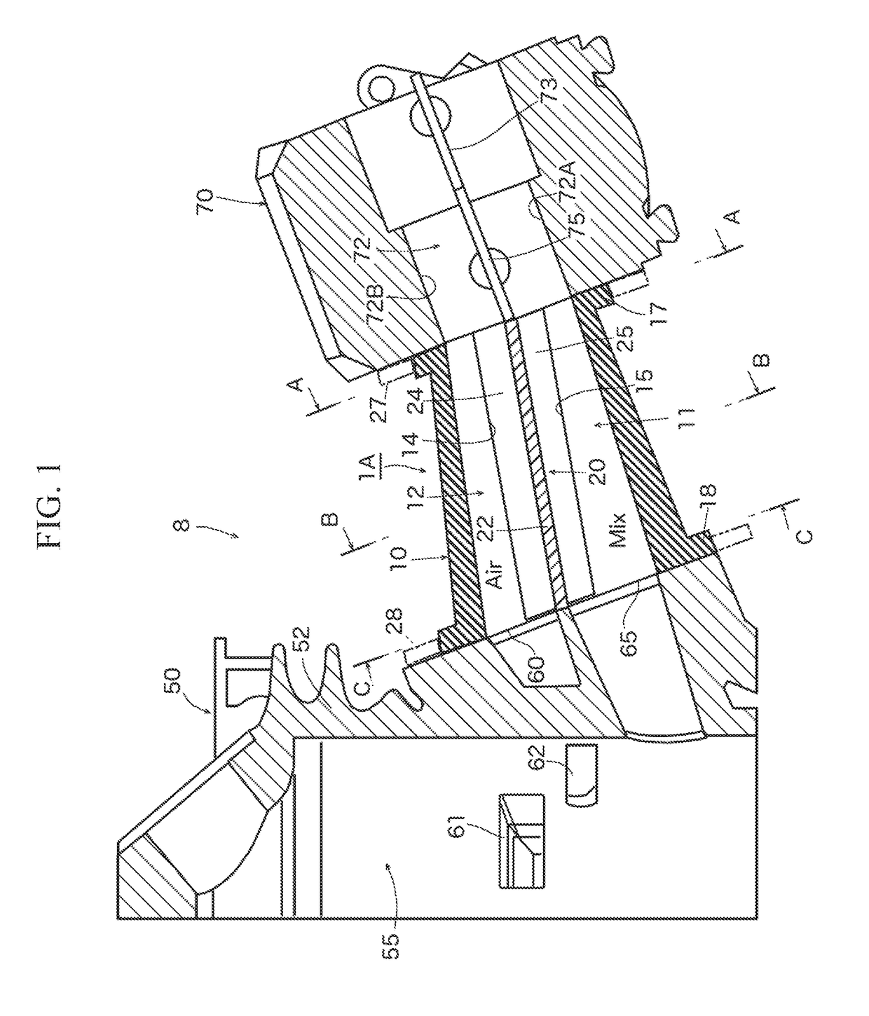
[0043]FIG. 1 is a schematic cross-sectional view showing the main part of a stratified scavenging two-stroke engine to which a first embodiment of a suction tube of a stratified scavenging engine according to the present invention is applied.

[0044]Regarding a stratified scavenging two-stroke engine 8 shown in the drawing as an example, since the configuration of the stratified scavenging two-stroke engine is well known, only portions related to the present invention will be briefly explained. A body portion 52 of a cylinder 50 that forms a main part of an engine main body has formed therein an air-fuel mixture port 65 that is opened and closed by means of a piston (not shown), an air port 60 that is, also by means of the piston, brought into communication with a left and right pair of scavenging ports 61 and 62, and an exhaust port (not shown). One combustion cycle is completed through two-strokes of the piston instead of individual strokes only for sucking air and only for discharg...

second embodiment

[0067]FIG. 5 is a schematic cross-sectional view showing the main part of the stratified scavenging two-stroke engine to which a second embodiment of the suction tube of the stratified scavenging engine according to the present invention is applied.

[0068]With respect to the stratified scavenging two-stroke engine 8 shown in the drawing as an example, the second embodiment has the same configurations as those of portions (cylinder 50, carburetor 70, and the like) of the first embodiment, except for a suction tube 1C. Thus, portions that correspond to those of the first embodiment are assigned the same reference numerals and overlapping explanations will be omitted, and the following explanation will focus on the differences between the suction tube 1A of the first embodiment and the suction tube 1C of the second embodiment.

[0069]As clearly understood from FIGS. 6A, 6B, 6C and 7 in addition to FIG. 5, the suction tube 1C of the second embodiment includes a cylindrical exterior member ...


PUM

PropertyMeasurementUnit
Deformation enthalpyaaaaaaaaaa

Abstract

A suction tube of a stratified scavenging engine that can improve the flexibility in designing the shapes and layouts of an air-fuel mixture passage and an air passage; allow for continuous and smooth changes in the shapes of the cross sections of the air-fuel mixture passage and the air passage from the inlet side toward the outlet side; reduce the number of components; and facilitate attachment and assembly; and that is also advantageous in terms of cost is provided. The suction tube includes an air-fuel mixture passage and an air passage, inlet and outlet sides of the passages being connected to a carburetor and a cylinder, respectively; a cylindrical exterior member that mainly forms an outer perimeter portion of each of the air-fuel mixture passage and the air passage; and an interior member for dividing the inside of the cylindrical exterior member into the air-fuel mixture passage and the air passage. With the use of elastic deformation of the interior member or the cylindrical exterior member, the interior member is attached to and integrally formed with the inside of the cylindrical exterior member.

Description

RELATED APPLICATIONS[0001]The present application claims priority from Japanese patent application JP 2016-142615 filed on Jul. 20, 2016, the content of which is hereby incorporated by reference into this application.BACKGROUND OF THE INVENTION1. Field of the Invention[0002]The present invention relates to a suction tube that also functions as an insulator and that is disposed between an engine main body (cylinder) and a carburetor of a stratified scavenging engine, and particularly relates to a suction tube, which has an air-fuel mixture passage and an air passage for stratified scavenging, of a stratified scavenging engine.2. Description of the Related Art[0003]Traditionally, stratified scavenging two-stroke engines, which are advantageous in complying with exhaust gas emission regulations of various countries, have been often used as power sources for portable power working machines such as a brush cutter and a chain saw. Some of such stratified scavenging two-stroke engines have...

Claims


Application Information

Patent Timeline
IPC IPC(8): F02M19/06F02M23/00F02F1/22F02B25/02
CPCF02M19/06F02F1/22F02M23/001F02B25/02F02B17/00F02B25/04F02B25/22F02B33/04F02B33/44F02M35/10078F02M35/1019F02M35/10196F02M35/10255F02M35/10262F02M35/10268F02M35/10321Y02T10/12
Inventor YONEYAMA, KAZUHIROMIYAZAKI, HIROSHI
Owner YAMABIKO CORP
Why Eureka
Try Eureka