Folded Camera
a camera and lens technology, applied in the field of camera systems, can solve the problems of chromatic aberration and field curvature of conventional small cameras used in such devices, and achieve the effects of reducing or eliminating interference of environmental noise, and correcting chromatic aberration and field curvatur
- Summary
- Abstract
- Description
- Claims
- Application Information
AI Technical Summary
Benefits of technology
Problems solved by technology
Method used
Image

Examples
Embodiment Construction
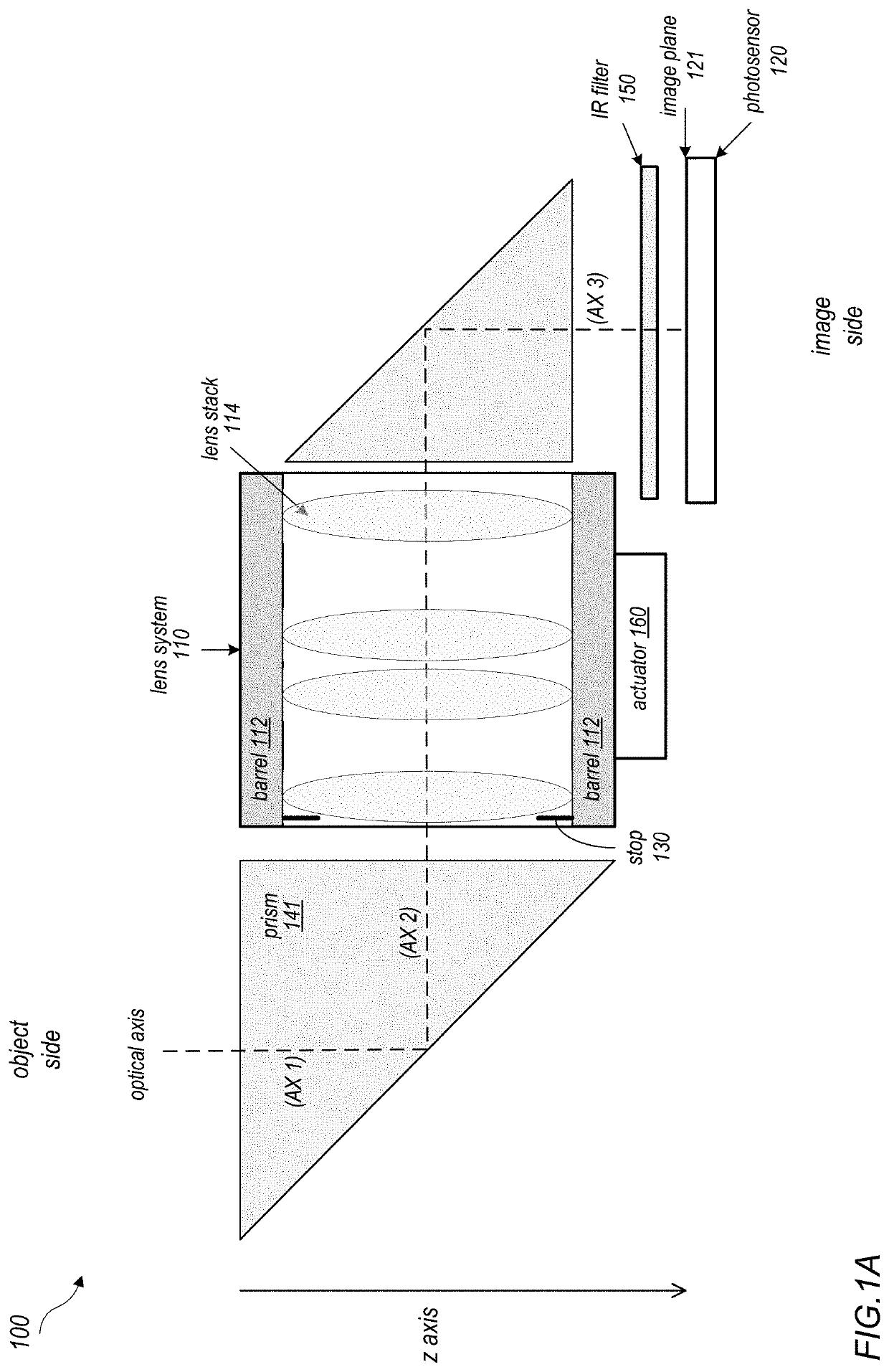
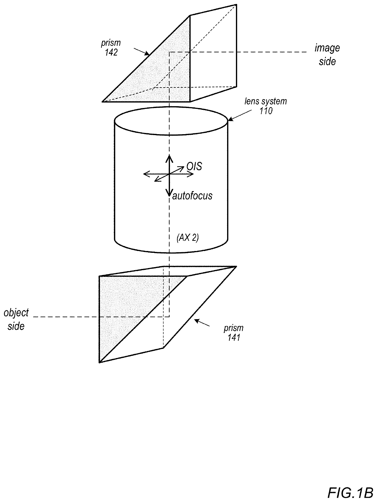
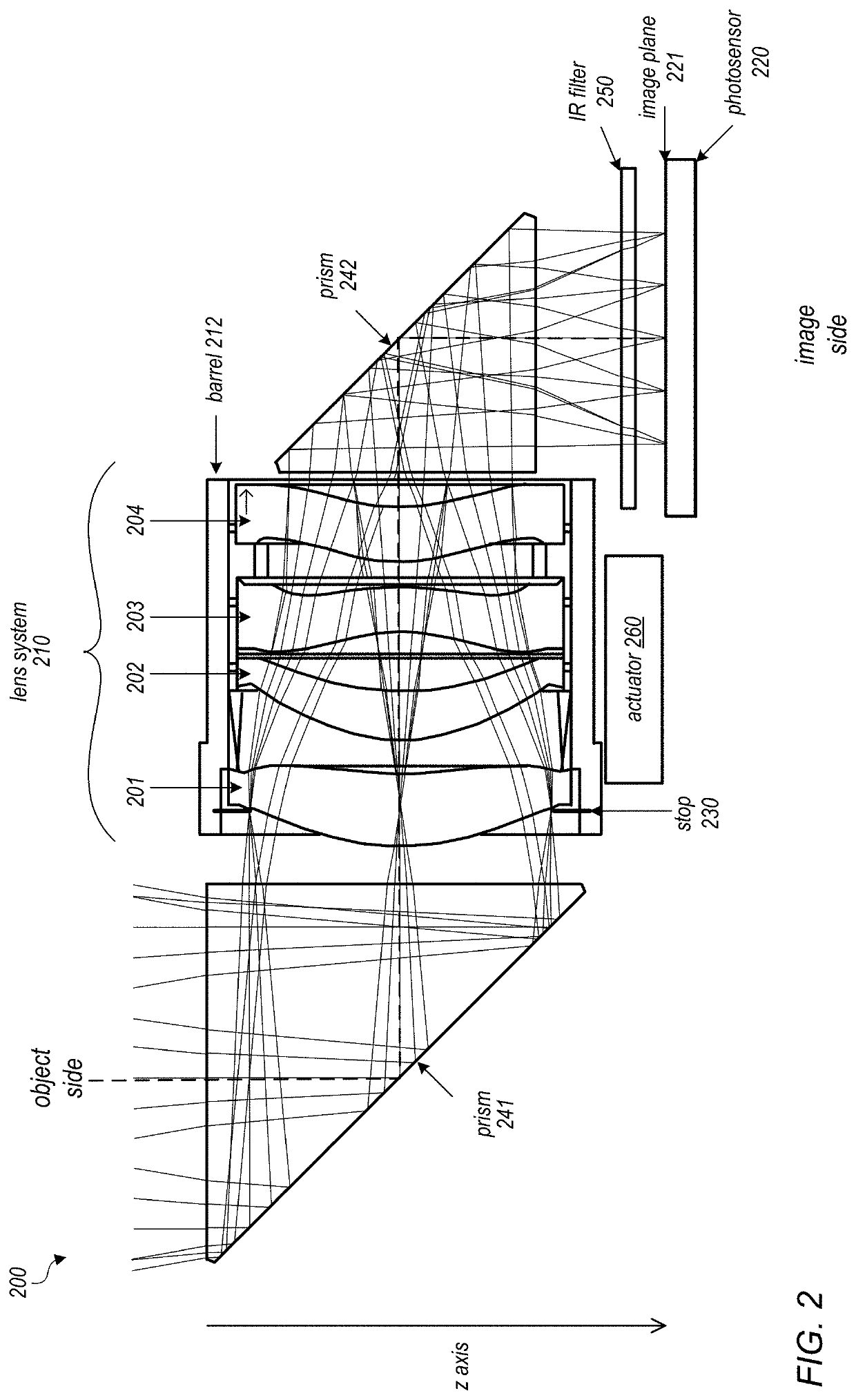
[0004]Embodiments of the present disclosure may provide a folded camera that may, for example, be used in small form factor cameras. Embodiments of a folded camera are described that include two light folding elements (e.g., prisms) and an independent lens system located between the two prisms that includes an aperture stop and lens elements with refractive power mounted in a lens barrel. The prisms and lens system may collectively be referred to as an optical system. The prisms provide a “folded” optical axis for the camera, for example to reduce the Z-height of the camera. The lens system includes a lens stack including one or more refractive lens elements mounted in a lens barrel, and an aperture stop located at or in front of a first lens element in the stack. A first prism redirects light from an object field from a first axis (AX 1) to the lens system on a second axis (AX 2). The lens element(s) in the lens stack receive the light through the aperture stop and refract the ligh...
PUM
 Abstract
Description
Claims
Application Information