

Power prism for folded lenses
a lens system and power prism technology, applied in the field of camera systems, can solve the problems affecting the image quality of the camera, and the resolution of the image captured by the conventional small camera used in such devices, etc., and achieve the effect of reducing the z-height of the lens system and the z-height of the camera
- Summary
- Abstract
- Description
- Claims
- Application Information
AI Technical Summary
Benefits of technology
Problems solved by technology
Method used
Image

Examples
Embodiment Construction
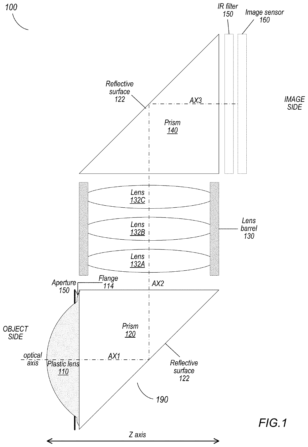
[0004]Embodiments of an optical prism with refractive power for folded lens systems are described that may, for example, be used in small form factor cameras in mobile multipurpose devices such as smartphones and tablet or pad devices. A folded lens system may include one or more prisms and a lens stack including one or more refractive lens elements. A first prism redirects light from a first optical axis to a second optical axis to thus provide a “folded” optical axis for the lens system. Using a prism to fold the optical axis may, for example, reduce the Z-height of the lens system, and thus may reduce the Z-height of a camera that includes the lens system. In some folded lens systems, a second prism may be located at the image side of the lens stack to fold the optical axis on to a third axis.
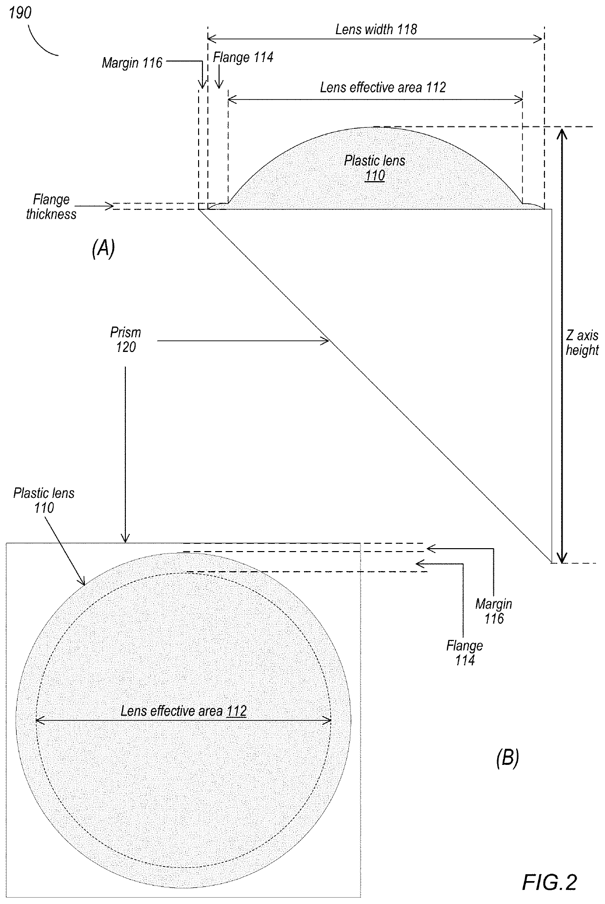
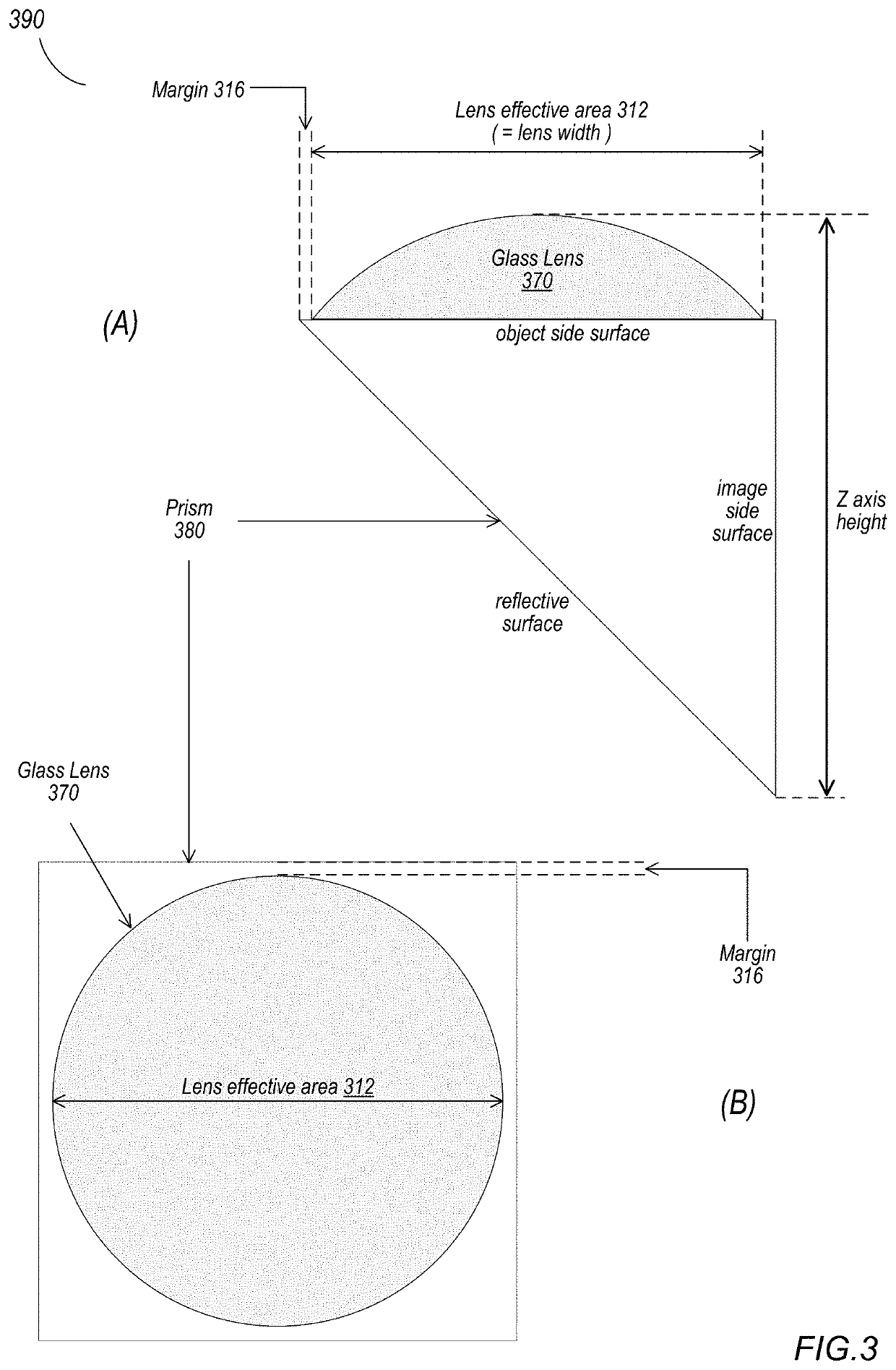
[0005]In some folded lens systems, a prism with refractive power (referred to as a power prism) may be used. For example, in some camera designs, a folded lens system may require a lens on t...
PUM
| Property | Measurement | Unit |
|---|---|---|
| height | aaaaa | aaaaa |
| thickness | aaaaa | aaaaa |
| thickness | aaaaa | aaaaa |
Abstract
Description
Claims
Application Information