

Optical prism with interlock
a lens system and optical technology, applied in the field of camera systems, can solve the problems of lower image quality and/or resolution of conventional small cameras used in such devices, and achieve the effect of reducing the z-height of the lens system and the z-height of the camera
- Summary
- Abstract
- Description
- Claims
- Application Information
AI Technical Summary
Benefits of technology
Problems solved by technology
Method used
Image

Examples
Embodiment Construction
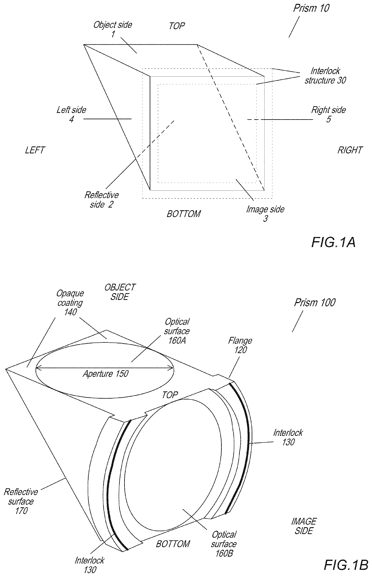
[0004]Embodiments of an optical prism with interlock for folded lens systems are described. A folded lens system may, for example, be used in small form factor cameras in mobile multipurpose devices such as smartphones and tablet or pad devices. A folded lens system may include a prism and a lens stack including one or more refractive lens elements. The prism redirects light from a first optical axis to a second optical axis to thus provide a “folded” optical axis for the lens system. Using the prism to fold the optical axis may, for example, reduce the Z-height of the lens system, and thus may reduce the Z-height of a camera that includes the lens system.
[0005]In some embodiments, the folded lens system may include, from an object side to an image side, a prism and a lens stack including one or more refractive lenses. A reflective surface of the prism provides a folded optical axis for the lens system by bending the optical axis (e.g., by 90 degrees) to reduce the Z-height of the l...
PUM
| Property | Measurement | Unit |
|---|---|---|
| Abbe number | aaaaa | aaaaa |
| optical | aaaaa | aaaaa |
| movement | aaaaa | aaaaa |
Abstract
Description
Claims
Application Information