
Drain arrangement

a technology of drain arrangement and drain, which is applied in the direction of valve housing, valve operating means/releasing devices, mechanical equipment, etc., can solve the problems of occupying only little installation space and a relatively large structural space, and achieves compact structure, reduces the space required below the sanitary item, and minimizes the height of the drain arrangement

Active Publication Date: 2021-11-18
GEBERIT INT AG
View PDF1 Cites 2 Cited by
  • Summary
  • Abstract
  • Description
  • Claims
  • Application Information

AI Technical Summary

Benefits of technology

The patent text describes how the placement of the mouth and outlet openings on a drain valve housing and the associated outflow pipe minimizes the amount of space needed for the drain arrangement. This results in better use of the space below the sanitary item and allows for a more compact drain valve arrangement. Additionally, the small distance between the outflow pipe further reduces the required space for the valve arrangement, making it more compact in its width.

Problems solved by technology

Although EP 2 045 403 has numerous advantages, it is a disadvantage that the structural space covers a relatively large area in the downward direction, this being disadvantageous for the volume of a base cabinet which is to be arranged below the washbasin.
For example, a key requirement is the compactness of a drain arrangement, so that the latter takes up only little installation space.

Method used


Image

  • Drain arrangement
  • Drain arrangement
  • Drain arrangement

Examples


Embodiment Construction

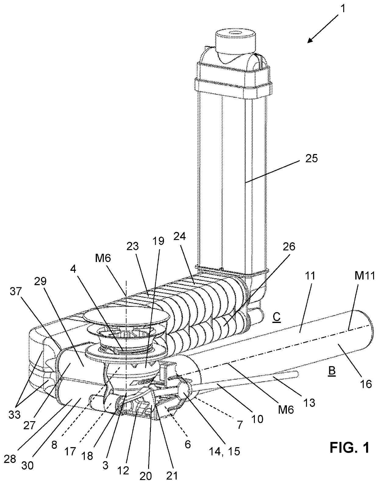
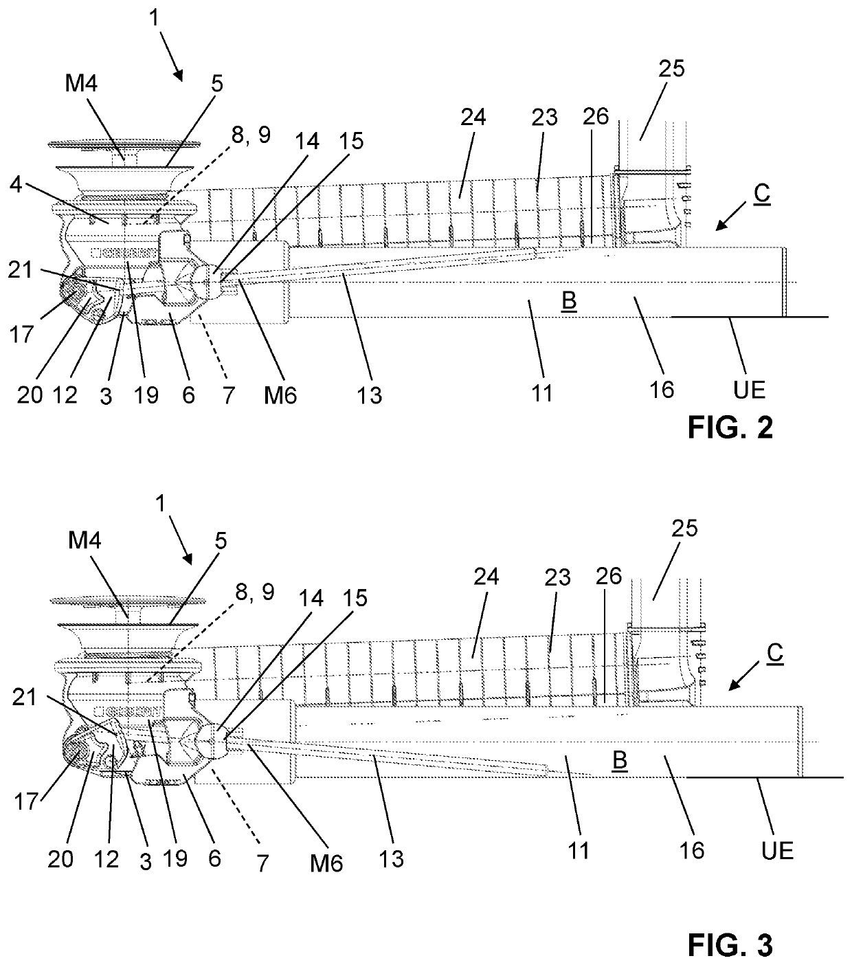
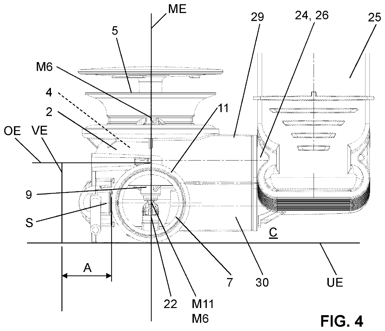
[0069]FIGS. 1 to 10 show various views of a preferred embodiment of a drain arrangement according to the invention. FIGS. 1 to 9 show a first variant of the preferred embodiment, and FIG. 10 shows a variant thereof.

[0070]The drain valve arrangement 1 serves for connection to a sanitary item 2. The sanitary item 2 is preferably a washbasin or a sink. The drain arrangement 1 comprises a drain valve housing 3 having a first channel section 4 with an inlet opening 5, having a second channel section 6 with an outlet opening 7, and having a valve seat 8 situated between the inlet opening 5 and the outlet opening 7. The drain valve arrangement 1 furthermore comprises a valve body 9 which is movable from the valve seat 8 from a closed position into an open position and back. The valve body 9 is moved from the closed position into the open position by way of an actuating unit 10. The drain valve arrangement 1 furthermore comprises an outflow pipe 11 into which the second channel section 6 op...


PUM


Abstract

A drain arrangement that comprises a drain valve housing which has a first channel section with an inlet opening, a second channel section with an outlet opening, and a valve seat situated between the inlet opening and the outlet opening. There also is a valve body, an actuating unit by way of which the valve body is movable, and an outflow pipe into which the second channel section opens by way of the outlet opening thereof. A first central axis extends centrally through the first channel section, and an outflow pipe central axis extends centrally through the outflow pipe. The outflow pipe central axis intersects the first central axis, and the drain arrangement furthermore comprises an overflow unit, which has a first connecting pipe, an overflow pipe and a second connecting pipe.

Description

TECHNICAL FIELD[0001]The present invention relates to a drain arrangement for a sanitary item, in particular for a washbasin or a sink, according to claim 1.PRIOR ART[0002]Drain arrangements for washbasins or sinks are known from the prior art.[0003]For example, EP 2 045 403 discloses a drain arrangement having an overflow unit. The overflow unit extends by way of connecting pipes away from a drain valve housing and upwards counter to the plumb-line direction. In the downward direction, the drain valve housing has a pipe connector, which is followed by a siphon and a drain line.[0004]Although EP 2 045 403 has numerous advantages, it is a disadvantage that the structural space covers a relatively large area in the downward direction, this being disadvantageous for the volume of a base cabinet which is to be arranged below the washbasin.[0005]Various requirements for drain arrangements emerge from practical experience. For example, a key requirement is the compactness of a drain arran...

Claims


Application Information

Patent Timeline
Patent Type & Authority Applications(United States)
IPC IPC(8): E03C1/232E03C1/242
CPCE03C1/232E03C1/242F16K1/00F16K1/32F16K31/465F16K1/36F16K27/02E03C1/2304
Inventor OBERHOLZER, MARCOCULATTI, ROMAN
Owner GEBERIT INT AG
Learn More