
Vapor injected piston compressor

a piston compressor and vapor injection technology, applied in the field of compressors, can solve the problems of increasing occupying a larger amount of space, and a larger compressor with a larger maximum displacement, so as to increase the maximum displacement of the compressor and the cost of manufacture, and maximize the efficiency of the compressor

Active Publication Date: 2021-12-16
HANON SYST
View PDF6 Cites 0 Cited by
  • Summary
  • Abstract
  • Description
  • Claims
  • Application Information

AI Technical Summary

Benefits of technology

The present invention is about a new type of compressor that reduces the amount of work it has to do while still being very efficient. This is done by using a special design that minimizes the size of the compressor and reduces the cost of manufacturing it.

Problems solved by technology

However, increasing displacement of the compressors can be problematic.
First, a compressor with a larger maximum displacement occupies a larger amount of space.
Second, increasing the maximum displacement of the compressor results in a greater mass of the compressor (i.e. additional material and components) which increases a cost of manufacture.
Third, for variable displacement compressors, an efficiency of the compressor is decreased with an increase in maximum displacement of the compressor.
As the maximum displacement increases, a bore-to-stroke ratio decreases in the variable mode which results in high power and energy consumption for heating and / or cooling.
The higher the power and energy consumption, the greater the undesired emissions from the vehicle.
However, including vapor injected technology with piston compressors has typically been problematic.
This results in previously expended work to be lost.
Other attempts at introducing vapor to the compressor typically result in increased clearance or dead volume of the cylinders in the cylinder bores which also decreases the efficiency of the compressor and increases in undesired emissions.

Method used


Image

  • Vapor injected piston compressor
  • Vapor injected piston compressor
  • Vapor injected piston compressor

Examples


Embodiment Construction

[0020]The following detailed description and appended drawings describe and illustrate various embodiments of the invention. The description and drawings serve to enable one skilled in the art to make and use the invention, and are not intended to limit the scope of the invention in any manner. In respect of the methods disclosed, the steps presented are exemplary in nature, and thus, the order of the steps is not necessary or critical.

[0021]A″ and “an” as used herein indicate “at least one” of the item is present; a plurality of such items may be present, when possible. Spatially relative terms, such as “front,”“back,”“inner,”“outer,”“bottom,”“top,”“horizontal,”“vertical,”“upper,”“lower,”“side,”“above,”“below,”“beneath,” and the like, may be used herein for ease of description to describe one element or feature's relationship to another element(s) or feature(s) as illustrated in the figures. Spatially relative terms may be intended to encompass different orientations of the device ...


PUM


Abstract

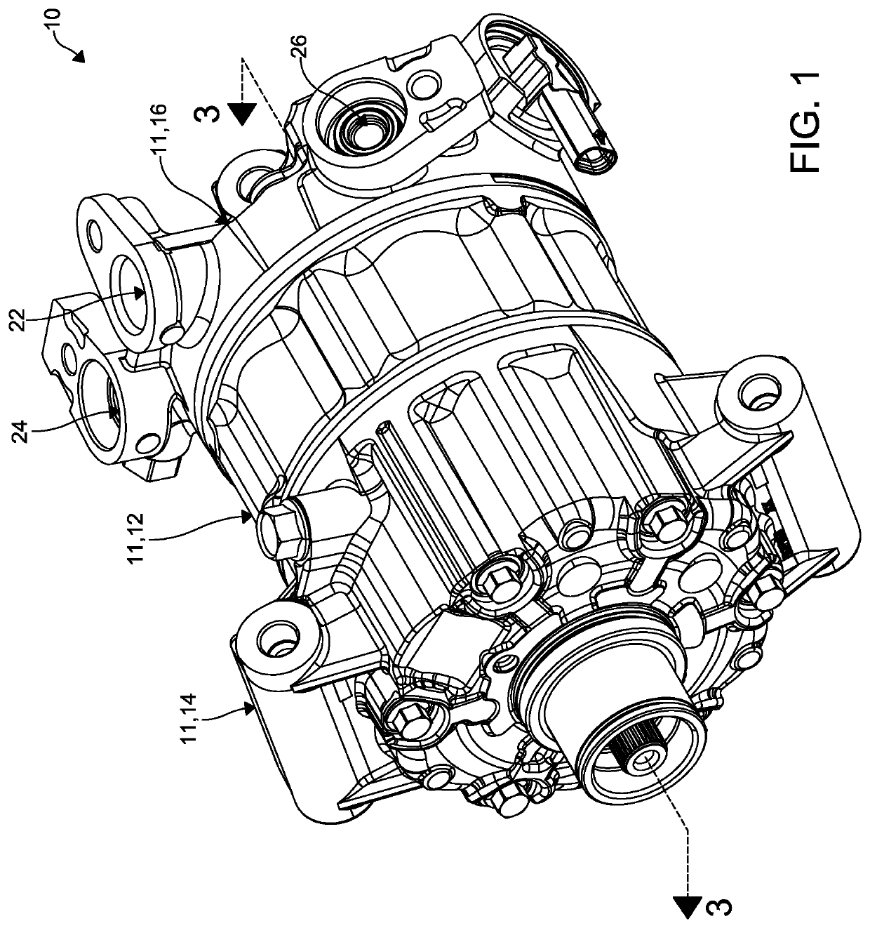
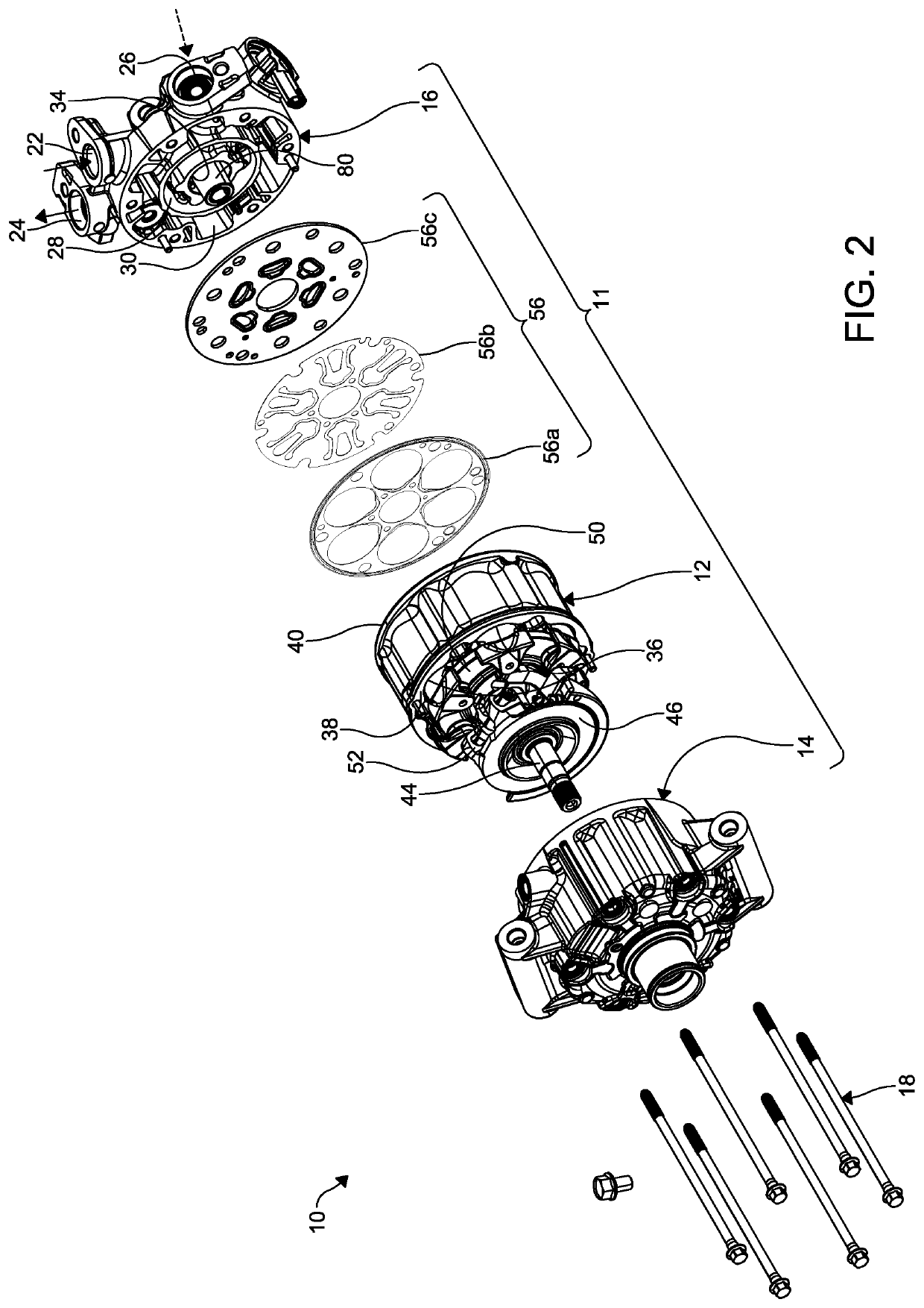
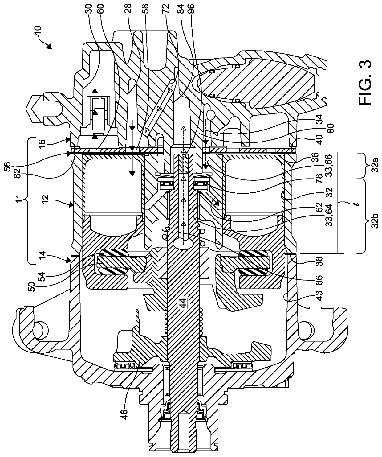
A piston type compressor has a main housing including a cylinder housing. The cylinder housing has a central bore for receiving a shaft therein through a first surface thereof and a plurality of bores configured for receiving a plurality of pistons therein through the first surface thereof. An inlet is configured for conveying a primary fluid to the plurality of bores. An outlet is configured for conveying the primary fluid from the plurality of bores. A plurality of passages is separate from the inlet and the outlet. Each of the plurality of passages is formed in the main housing and is configured for conveying a supplemental fluid to one of the plurality of bores.

Description

FIELD OF THE INVENTION[0001]The invention relates to compressors and particularly to a vapor injected piston compressor having ports directly injecting fluid into a cylinder housing of the compressor.BACKGROUND OF THE INVENTION[0002]As commonly known, vehicles typically include a heating, ventilating, and air conditioning (HVAC) system. The HVAC system maintains a temperature within a passenger compartment of the vehicle at a comfortable level for a passenger by providing a desired heating, cooling, and ventilation to the passenger compartment. The HVAC system conditions air flowing therethrough and distributes the conditioned air throughout the passenger compartment.[0003]Piston type, variable or fixed, refrigerant compressors are commonly employed in HVAC systems of vehicles. These compressors are typically sized, designed, and configured depending on the application. One of the factors in determining the size, design, and configurations of the compressors is the displacement of c...

Claims


Application Information

Patent Timeline
IPC IPC(8): F04B27/10
CPCF04B27/1045F04B27/10F04B27/1009F04B27/0891F04B27/1081F04B27/0878F04B27/0895F05B2210/12F04B27/1018
Inventor THEODORE, JR., MICHAEL G.BHATIA, KANWALCORDY, CARL
Owner HANON SYST
Learn More