Vacuum cleaner system and dangerous position posting method
- Summary
- Abstract
- Description
- Claims
- Application Information
AI Technical Summary
Benefits of technology
Problems solved by technology
Method used
Image

Examples
specific example 1
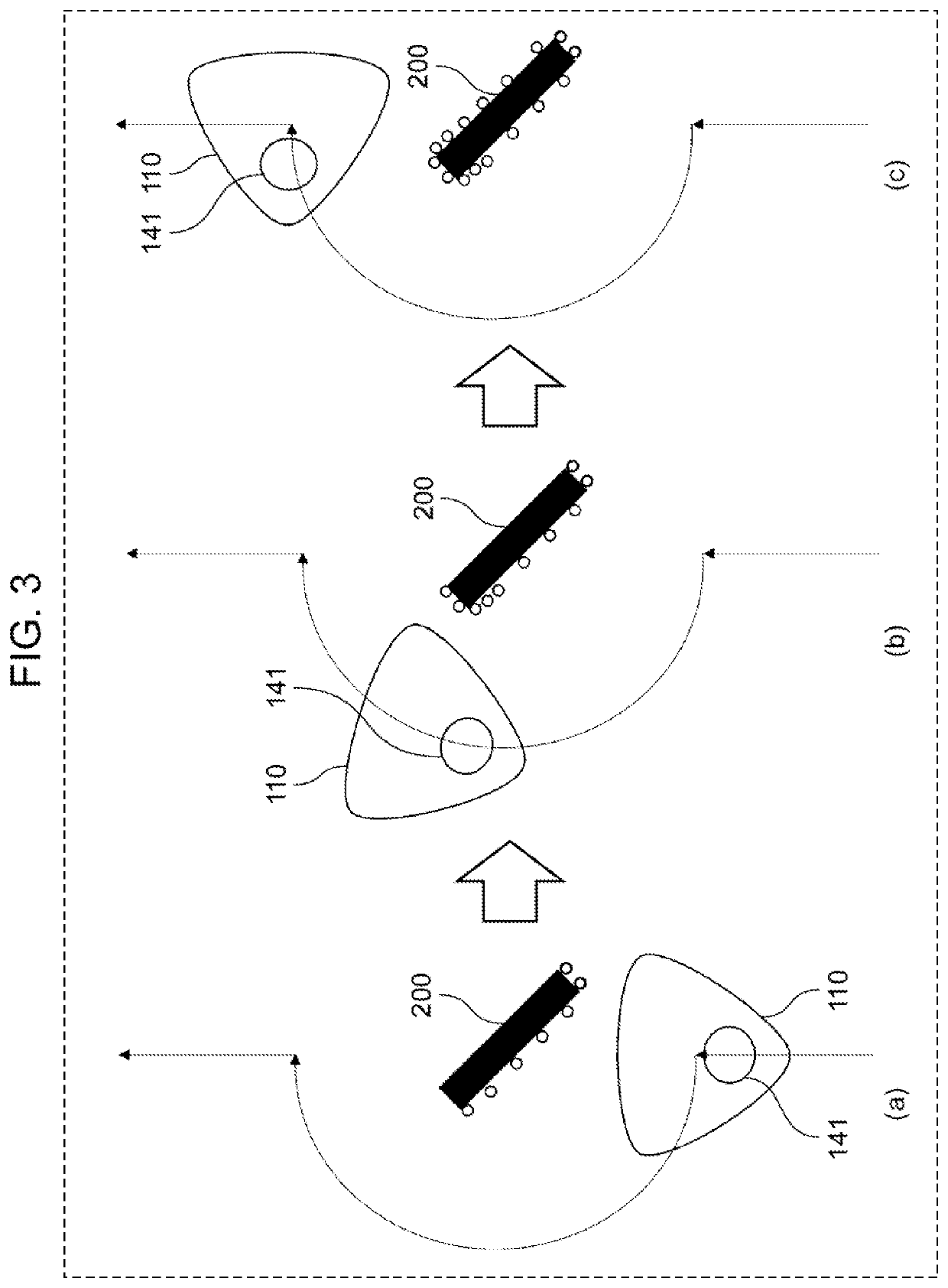
[0053]Specific example 1 of generation of object information and determination by danger determination unit 122 based on the object information will be described next with reference to FIGS. 7 and 3.
[0054]FIG. 7 is a flowchart illustrating the procedure of processing in vacuum cleaner system 100 when vacuum cleaner 110 according to the present exemplary embodiment performs information acquisition running in the middle of normal cleaning running. Note that the flowchart shown in FIG. 7 and the description of the following procedure show an example of processing of vacuum cleaner system 100 in the present exemplary embodiment, and the order of steps may be changed, another step may be added, or some steps may be deleted.
[0055]Running controller 101 acquires the self-position of vacuum cleaner 110 from sensing unit 106, and receives, for example, information representing the map created by SLAM from creation recognition unit 103 (S101). Next, running controller 101 starts cleaning runn...
specific example 2
[0062]Specific example 2 of generation of object information and determination by danger determination unit 122 based on the object information will be described next with reference to FIG. 8. FIG. 8 is a schematic view illustrating a state in which running vacuum cleaner 110 according to the exemplary embodiment approaches a descending step.
[0063]In specific example 2, as shown in FIG. 8, vacuum cleaner 110 includes a downward distance measuring sensor as first sensor 141 on the lower surface of the main body of vacuum cleaner 110. The downward distance measuring sensor is a sensor that measures the distance from the lower surface of vacuum cleaner 110 to the floor surface. Note that the type of downward distance measuring sensor is not particularly limited, and an infrared distance measuring sensor, a time of flight (TOF) sensor, or the like can be exemplified as the downward distance measuring sensor. When vacuum cleaner 110 moves forward based on a running instruction from runni...
specific example 3
[0065]Specific example 3 of generation of object information and determination by danger determination unit 122 based on the object information will be described next with reference to FIG. 9. FIG. 9 is a schematic view illustrating a state in which running vacuum cleaner 110 according to the exemplary embodiment approaches an ascending step having a relatively low height. In Specific Example 3, an ascending step having a relatively low height is not a step having a height that cannot be climbed over by a person such as a wall, but is an edge portion of object 200 such as a rug mat or a cushion on which a person can normally ride.
[0066]In Specific Example 3, as shown in FIG. 9, vacuum cleaner 110 includes a front downward distance measuring sensor as first sensor 141 on the front surface of the main body of vacuum cleaner 110. The front downward distance measuring sensor is a sensor that measures the distance between the floor surface in front of vacuum cleaner 110 in the running di...
PUM
 Abstract
Description
Claims
Application Information
 - R&D Engineer
- R&D Manager
- IP Professional
- Industry Leading Data Capabilities
- Powerful AI technology
- Patent DNA Extraction
Browse by: Latest US Patents, China's latest patents, Technical Efficacy Thesaurus, Application Domain, Technology Topic.
© 2024 PatSnap. All rights reserved.Legal|Privacy policy|Modern Slavery Act Transparency Statement|Sitemap