
System and method for monitoring and securing communications networks and associated devices

Pending Publication Date: 2022-02-24
INTRUSION
View PDF0 Cites 3 Cited by
  • Summary
  • Abstract
  • Description
  • Claims
  • Application Information

AI Technical Summary

Benefits of technology

[0015]In accordance with a further aspect of the invention, a method for shielding a network from malicious or unauthorized activity comprises: monitoring a network capable of transferring at least one data packet between a first network location and a second network location; isolating a first node operably associated with the first network location from a second node operably associated with the second network location; monitoring the at least one data packet, the first node, and the second node to independently determine whether the at least one data packet, the first node, and the second node, respectively, are trusted; allowing a request for connection between the first and second nodes a

Problems solved by technology

However, these monitoring solutions can also be ineffective, as there is no provision for the monitor to guarantee the source device.
Additionally, compromised hosts will typically ignore such redirections and communicate directly, thus bypassing the monitor.
The limitation of this approach is that of compatibility and coverage.
There are also compatibility issues, where some devices can't be spoofed with spoofed ARP responses.
Additionally, such type of mode is not capable of protecting computers within an enclave from each other or monitoring peer-to-peer communications within an enclave.
The DHCP solution mode overcomes some of the limitations of ARP spoofing mode but suffers from some of the same problems.
For instance, many devices on a network are configured with static IP addresses, therefore DHCP mode cannot be used to cause these nodes to participate by picking up the alternate router's IP

Method used


Image

  • System and method for monitoring and securing communications networks and associated devices
  • System and method for monitoring and securing communications networks and associated devices
  • System and method for monitoring and securing communications networks and associated devices

Examples


Example

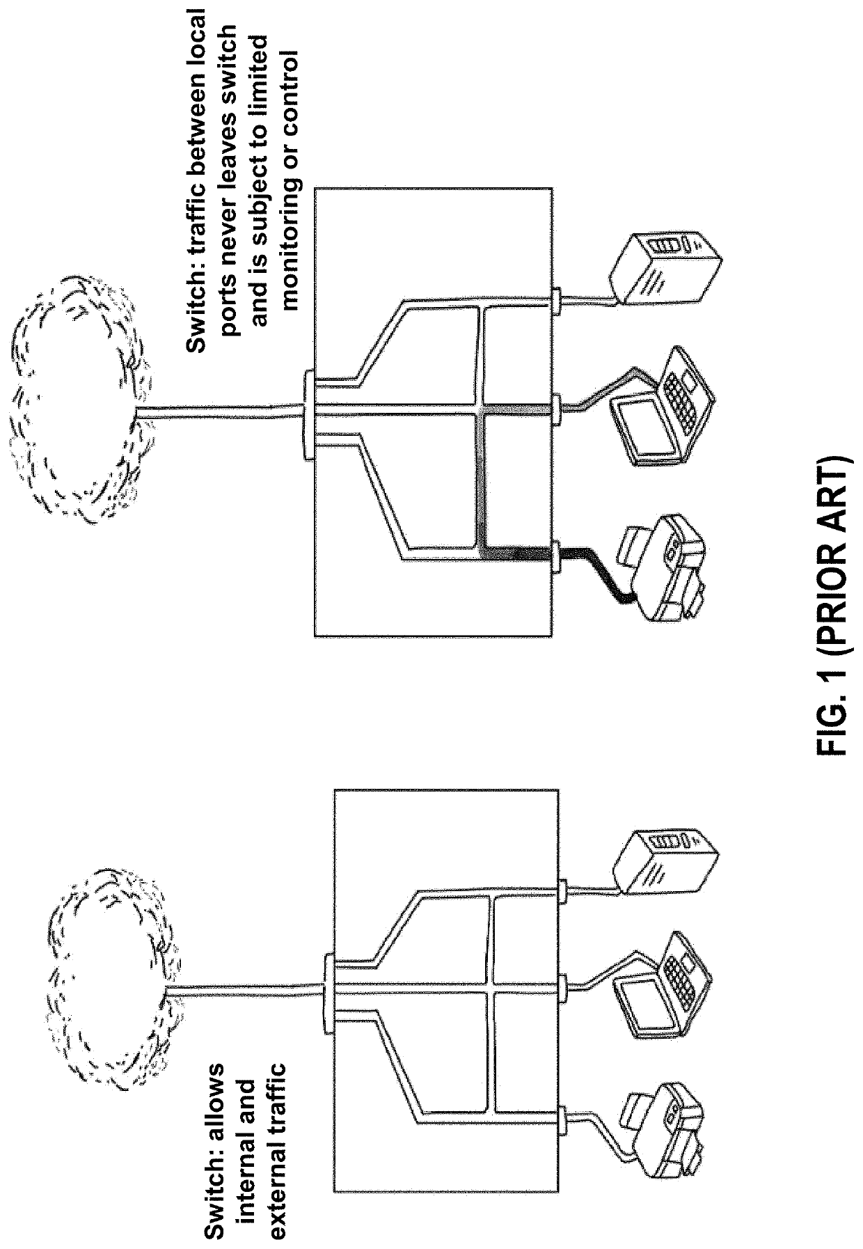
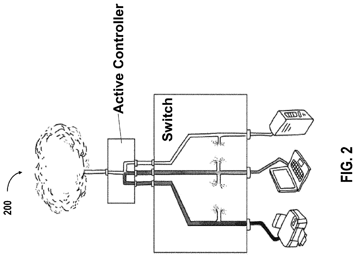
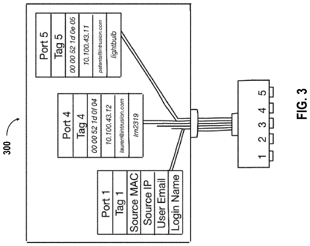
[0057]It is noted that the drawings are intended to depict exemplary embodiments of the invention and therefore should not be considered as limiting the scope thereof. The invention will now be described in greater detail with reference to the accompanying drawings.

DETAILED DESCRIPTION OF THE INVENTION

[0058]In the following detailed description, reference is made to the accompanying figures, which form a part hereof. In the figures, similar symbols typically identify similar components, unless context dictates otherwise. The illustrative embodiments described in the detailed description, figures, and claims are not meant to be limiting. Other embodiments may be utilized, and other changes may be made, without departing from the scope of the subject matter presented herein. It will be readily understood that the aspects of the present disclosure, as generally described herein, and illustrated in the figures, can be arranged, substituted, combined, separated, and designed in a wide va...


PUM


Abstract

A system and method for shielding a network from malicious or unauthorized activity includes an active monitoring device connected to the network for monitoring each data packet and controlling the network connection. End devices connected to the network are isolated from each other so that data cannot flow in the event one or more data packets, devices, and so on, are flagged as untrustworthy. The active monitoring device uses the filter data to determine whether unusual behavior, unauthorized access, attempted hacking occurred, and ensure isolation between network devices and prevent transfer of data. Continuous monitoring ensures once trusted devices that abnormally change behavior are flagged as untrusted, thereby preventing breaches of the network.

Description

CROSS-REFERENCE TO RELATED APPLICATION[0001]This application claims priority to U.S. Provisional Application No. 63 / 068,148 filed on Aug. 20, 2020, and U.S. Provisional Application No. 63 / 177,818, filed on Apr. 21, 2021, which of which is entirely incorporated herein by reference.BACKGROUND[0002]Current network security models are grossly inadequate for ensuring complete immunity from security breaches. Companies and governments have gone through many paths and invested heavily in technology and people. However, the severity of breaches have steadily increased due to the ever-increasing sophistication of viruses, malware, ransomware, spyware, and the like, as well as the ever-increasing knowledge and skill level of persons, entities, and organizations that develop and deploy such devastating tactics for nefarious or other purposes. The security measures of current communications networks and the devices connected thereto can be reduced to a couple of simplified steps including: 1) l...

Claims


Application Information

Patent Timeline
IPC IPC(8): H04L29/06H04L12/46
CPCH04L63/1433H04L63/0245H04L63/0236H04L2212/00H04L63/1441H04L12/4645H04L63/0272H04L12/4633H04L12/4641H04L63/1483H04L61/103H04L61/2514H04L61/2575H04L61/5014H04L2101/622H04L61/4511H04L61/10H04L63/1466H04L63/029
Inventor HEAD, JR., TOMMY JOENEVIL, DARISHAMLYN, JEREMYDUMAS, BLAKEHEAD, LAUREN
Owner INTRUSION
Learn More