
Bump Steer Calculator

a calculator and bump steer technology, applied in vehicle suspension/damping testing, vehicle components, resilient suspensions, etc., can solve the problems of unfavorable bump steer, unstable steering, and unnecessary heating and wear of tires

Active Publication Date: 2022-03-10
ZMYEWSKI JUSTIN
View PDF2 Cites 0 Cited by
  • Summary
  • Abstract
  • Description
  • Claims
  • Application Information

AI Technical Summary

Benefits of technology

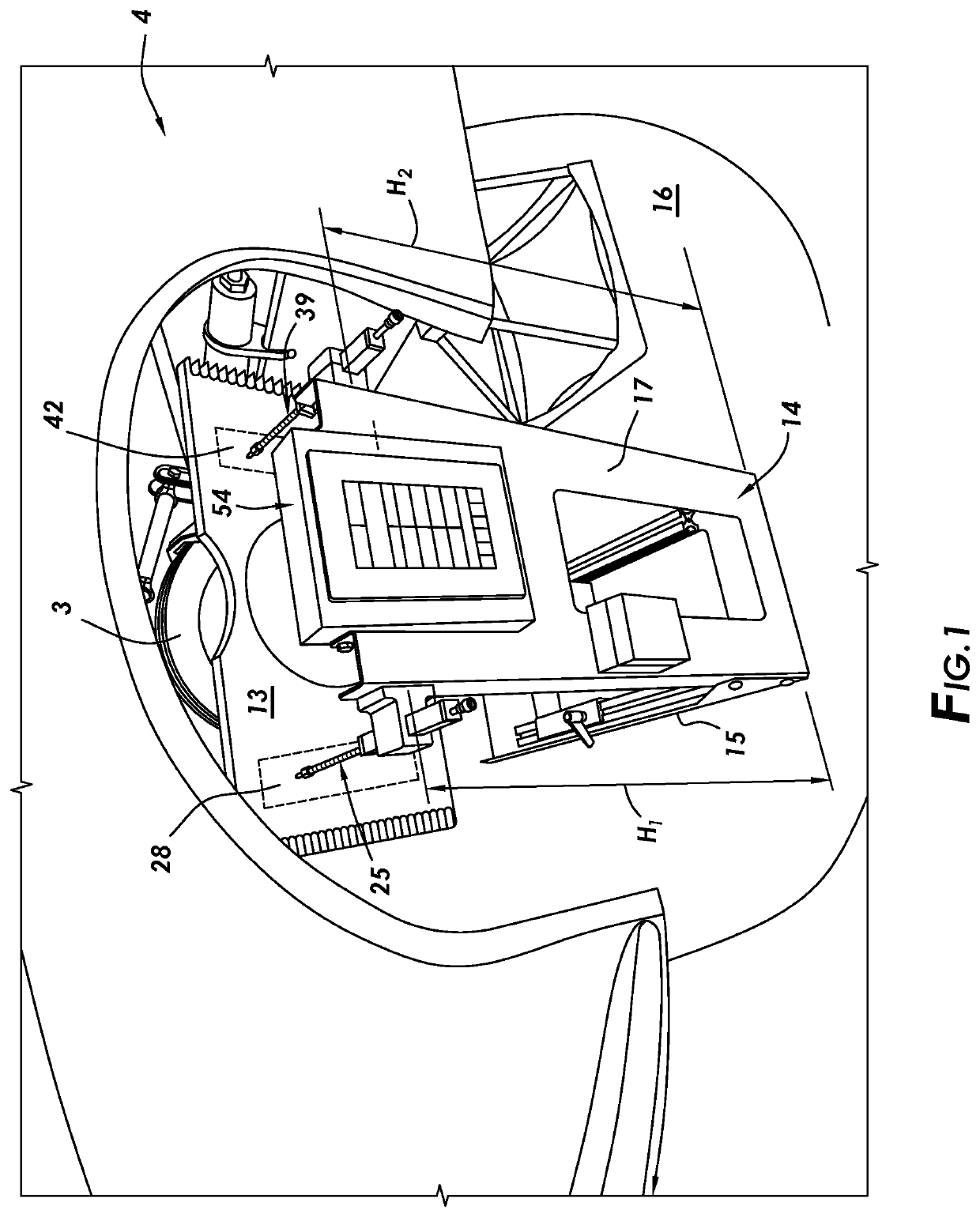
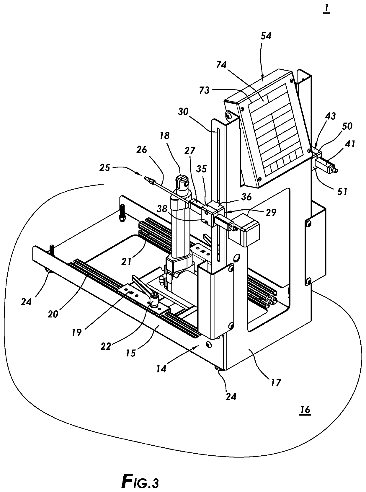
The invention is about a device that measures the movement of a vehicle's suspension during bumps. It includes a framework for supporting a linear actuator and two linear potentiometers. The device also includes a bump steer calculator that converts the data collected from the linear potentiometers into a measure of bump steer. This allows users to better understand and analyze the movement of the vehicle's suspension during bumps. The invention also includes a graphical user interface that displays the different components of the device and allows users to easily select and control them.

Problems solved by technology

Bump steer can be highly undesirable, especially within racing because braking, acceleration, roll, and transition over surfaces containing bumps all create movements that can magnify the effect of bump steer.
A vehicle suspension constantly transitioning between bump and droop, will constantly be shifting the steering angle of the vehicle and can make steering unstable.
Additionally, excessive bump steer can cause unnecessary heating and wear of the tires.
Tires move over bumps very quickly and the associated in and out toe oscillations generated by too much bump steer produces un-wanted tire heat, tire wear and steering instability.
Conventional apparatus to measure bump steer may lack sufficient accuracy or precision for fine adjustment of bump steer to eliminate unwanted self-steering of the vehicle, tire heat or wear.

Method used


Image

  • Bump Steer Calculator
  • Bump Steer Calculator
  • Bump Steer Calculator

Examples


Embodiment Construction

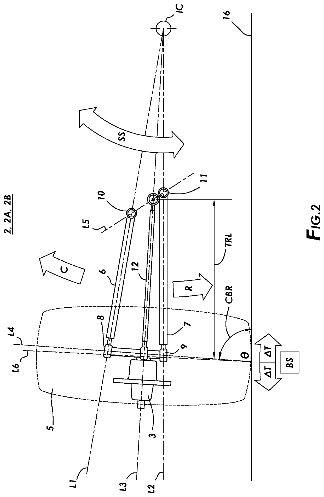
[0020]Generally, with reference to FIGS. 1 through 12, which depict a vehicle suspension bump steer measurement apparatus (1) (also referred to as the “apparatus”), a method of making a vehicle suspension bump steer measurement apparatus (1) and method of measuring bump steer (BS) in a vehicle suspension for productive management of bump steer (BS) throughout compression (C) and rebound (R) of a vehicle suspension (2).

[0021]“Compression (C)” as used herein refers to the constriction of the vehicle suspension (2) for example, as the result of hitting a bump.

[0022]“Rebound (R)” as used herein refers to the expansion of the vehicle suspension (2), for example when ‘rebounding’ from hitting a bump.

[0023]“Suspension Stroke (SS)” as used herein refers to the distance traveled by the vehicle suspension (2) from the bottom of the suspension stroke (SS) when a hub (3) of the vehicle suspension (2) hangs freely to the top of the suspension stroke (SS) when the hub (3) can no longer move in th...


PUM


Abstract

A vehicle suspension bump steer measurement apparatus and method of measuring bump steer in a vehicle suspension for productive management of toe change throughout compression and rebound of a vehicle suspension.

Description

I. FIELD OF THE INVENTION[0001]The present invention relates to a vehicle suspension bump steer measurement apparatus and method of measuring bump steer in a vehicle suspension for productive management of toe change throughout compression and rebound of the suspension system.II. BACKGROUND OF THE INVENTION[0002]Bump steer refers to the tendency of the wheel of a car to steer itself as it moves through the suspension stroke. Bump steer can be highly undesirable, especially within racing because braking, acceleration, roll, and transition over surfaces containing bumps all create movements that can magnify the effect of bump steer. A vehicle suspension constantly transitioning between bump and droop, will constantly be shifting the steering angle of the vehicle and can make steering unstable. Additionally, excessive bump steer can cause unnecessary heating and wear of the tires. Tires move over bumps very quickly and the associated in and out toe oscillations generated by too much bu...

Claims


Application Information

Patent Timeline
Patent Type & Authority Applications(United States)
IPC IPC(8): B60G17/016B60G3/20
CPCB60G17/016B60G3/202B60G3/20B60G2200/144B60G2206/93B60G2200/462B60G2200/4622B60G2500/30G01M17/04
Inventor ZMYEWSKI, JUSTIN
Owner ZMYEWSKI JUSTIN
Learn More