Augmented Rack and Pinion Steering System

a steering system and rack technology, applied in the direction of steering linkages, electrical steering, transportation and packaging, etc., can solve the problems of small unintended small dislocation of the rack, and small turn of the front wheels

Pending Publication Date: 2022-08-25
BANDY RONALD S
View PDF0 Cites 0 Cited by
  • Summary
  • Abstract
  • Description
  • Claims
  • Application Information

AI Technical Summary

Problems solved by technology

The slow steering ratio means that for a small rotation of the pinion shaft, the displacement of the rack is very small.
This way, a small rotation of the pinion shaft causes a very small displacement of the rack, which leads to a very small turn of the front wheels.
The small simulated rotation of the pinion shaft is reduced by the slow steering ratio and thereby causes a very small unintended disp

Method used


Image

  • Augmented Rack and Pinion Steering System
  • Augmented Rack and Pinion Steering System
  • Augmented Rack and Pinion Steering System

Examples


example two

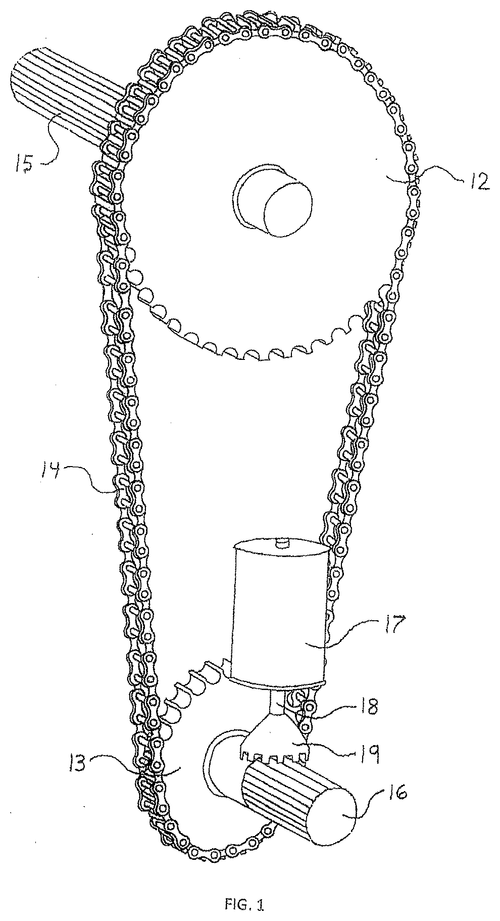
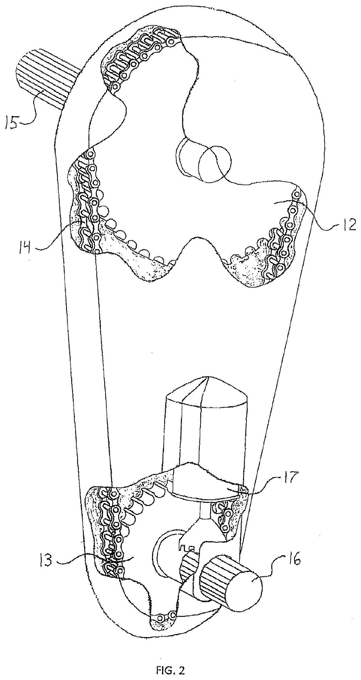
[0149] include the electric assist steering column in the steering system described in example one. The multiplied rotational torque is transmitted downstream in the order: electric assist steering column, augmented chain and sprocket assembly 11, electric assist motor box 22, and manual rack and pinion gearset 24 or ram assist rack and pinion gearset 30.

example three

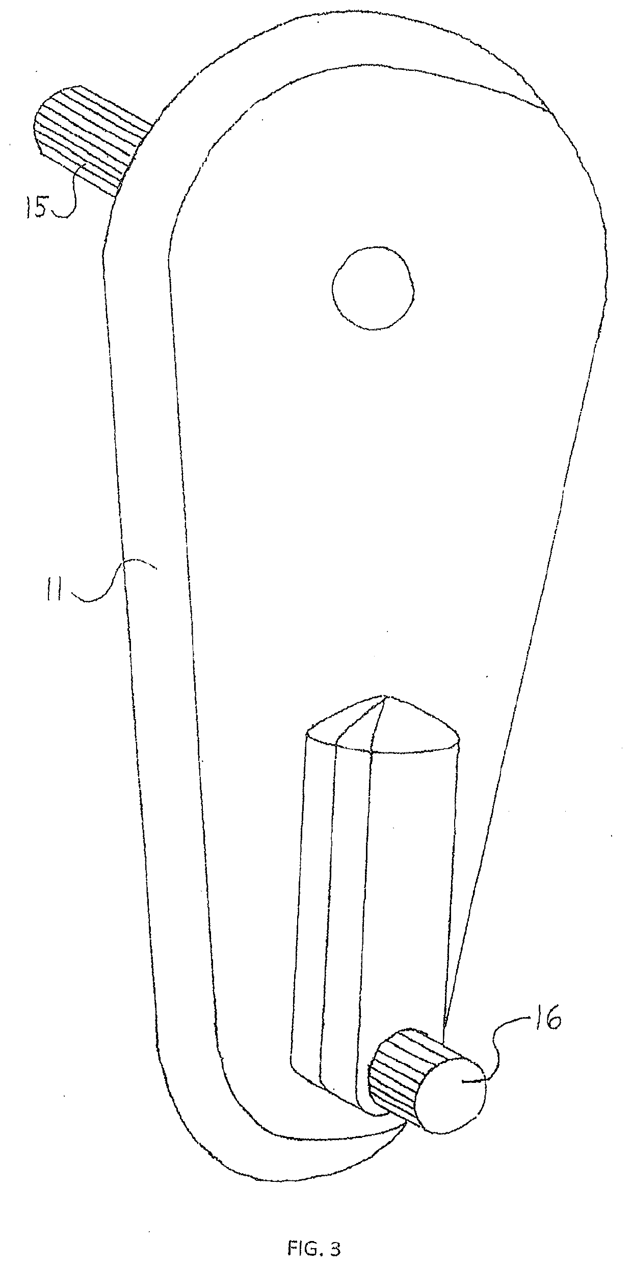
[0150] remove the electric motor 17 and electric assist motor box 22 from the steering system described in example two. The multiplied rotational torque is transmitted downstream in the order: electric assist steering column, augmented chain and sprocket assembly 63 (11 is converted into 63), and manual rack and pinion gearset 24 or ram assist rack and pinion gearset 30.

[0151]Conclusion from the three examples: the use of the electric assist steering column enables the electric motor 17 and electric assist motor box 22 to both be removed from the steering system without interrupting the flow of multiplied rotational torque from the electric assist steering column to the manual rack and pinion gearset 24 or ram assist rack and pinion gearset 30. In short, the use of the electric assist steering column enables the electric motor 17 and electric assist motor box 22 to both be removed from the steering system without interrupting the flow of multiplied rotational torque.

[0152]In effect,...


PUM


Abstract

The present invention is an improved version of the steering system described in U.S. patent application Ser. No. 17/115,573. The prior steering system features effortless steering input from the driver and negligible bumpsteer during suspension operation. Such extraordinary steering performance is realized with the use of costly and complex electric assist devices and control devices. The present steering system includes an alternative electric assist device which allows for the removal of the costly and complex electric assist devices in the prior steering system. The present steering system also includes a novel hydraulic control valve with a solenoid valve-plunger mechanism. The mechanism prevents premature wear or destruction of the rack and pinion gearset. The use of the alternative electric assist device and hydraulic control valve enables the present steering system to preserve the extraordinary steering performance featured in the prior steering system concurrent with a reduction in cost and complexity.

Description

CROSS-REFERENCE TO RELATED APPLICATIONS[0001]This application is a continuation-in-part of, and claims the benefit of priority to U.S. patent application Ser. No. 17 / 115,573, entitled “Augmented Rack And Pinion Steering System” filed on Dec. 8, 2020.STATEMENT REGARDING FEDERALLY SPONSORED RESEARCH OR DEVELOPMENT[0002]Not ApplicableREFERENCE TO SEQUENCE LISTING, A TABLE, OR A COMPUTER PROGRAM LISTING COMPACT DISC APPENDIX[0003]Not ApplicableBACKGROUND OF THE INVENTION[0004]The triangulated 4-link suspension system is the preferred front suspension system for a front solid axle four-wheel drive vehicle. A survey of the winningest, most competitive front solid axle four-wheel drive race vehicles quickly reveals that the front suspension system is based on the triangulated 4-link configuration. Despite such storied success in the off-road environment, the triangulated 4-link front (or rear) suspension system is not offered as a production-based or even as an optional performance-based s...

Claims


Application Information

Patent Timeline
IPC IPC(8): B62D5/22B62D5/04B62D3/12B62D1/16B62D5/06B62D7/18B62D5/065
CPCB62D5/22B62D5/0409B62D3/12B62D5/065B62D5/062B62D7/18B62D1/16B62D1/163B62D5/04B62D7/08
Inventor BANDY, RONALD S.
Owner BANDY RONALD S
Why Eureka
Try Eureka