Field controllable rotating electric machine system with magnetic excitation part

a technology of magnetic excitation and electric machine, which is applied in the direction of electric generator control, dynamo-electric converter control, mechanical energy handling, etc., can solve the problems of large energy loss, difficult control of the system, and inability to obtain optimal power in a wide rotational speed range. achieve the effect of field weakening control

Inactive Publication Date: 2009-02-19
KURA LAB
View PDF2 Cites 25 Cited by
  • Summary
  • Abstract
  • Description
  • Claims
  • Application Information

AI Technical Summary

Benefits of technology

[0012]Accordingly, an embodiment of the present invention advantageously provides a method for controlling a magnetic field strength, a rotating electric machine apparatus, and a rotating electric machine system, by which field-weakening control becomes easy, while satisfying the following conditions: (1) mechanical means are adopted for maintaining the operating condition; (2) generation of a magnetic force disturbing operation of the mecha...

Problems solved by technology

However, in both electric motors and electric generators, optimum power is not always obtained in a wide rotational speed range because of constant magnetic field strength from the field magnet.
In the case of the electric motor, the control thereof becomes difficult in a high-speed rotational region because the back electromotive force (power generation voltage) becomes too high, and therefore, various methods for weakening the field strength as field-weakening control have been proposed.
In the electric motor, field-weakening control by current phase control has been widely adopted, but energy loss is large because current flows that does not directly contribute to the rotation.
When current excitation for the control is used with a permanent magnet excitation, the structure of the rotating electric machine becomes complex and additionally ...

Method used


Image

  • Field controllable rotating electric machine system with magnetic excitation part
  • Field controllable rotating electric machine system with magnetic excitation part
  • Field controllable rotating electric machine system with magnetic excitation part

Examples


first embodiment

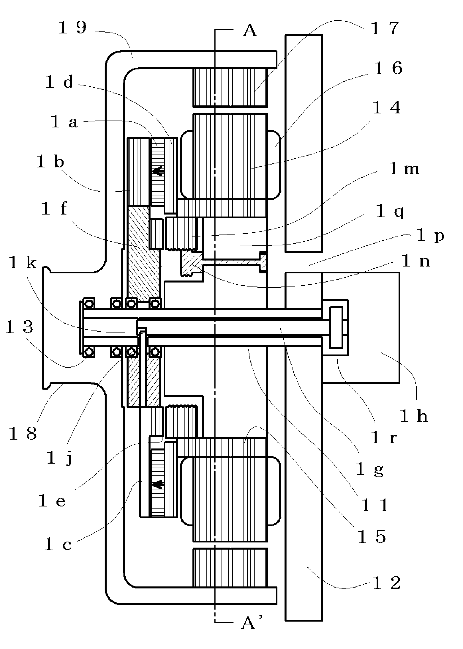
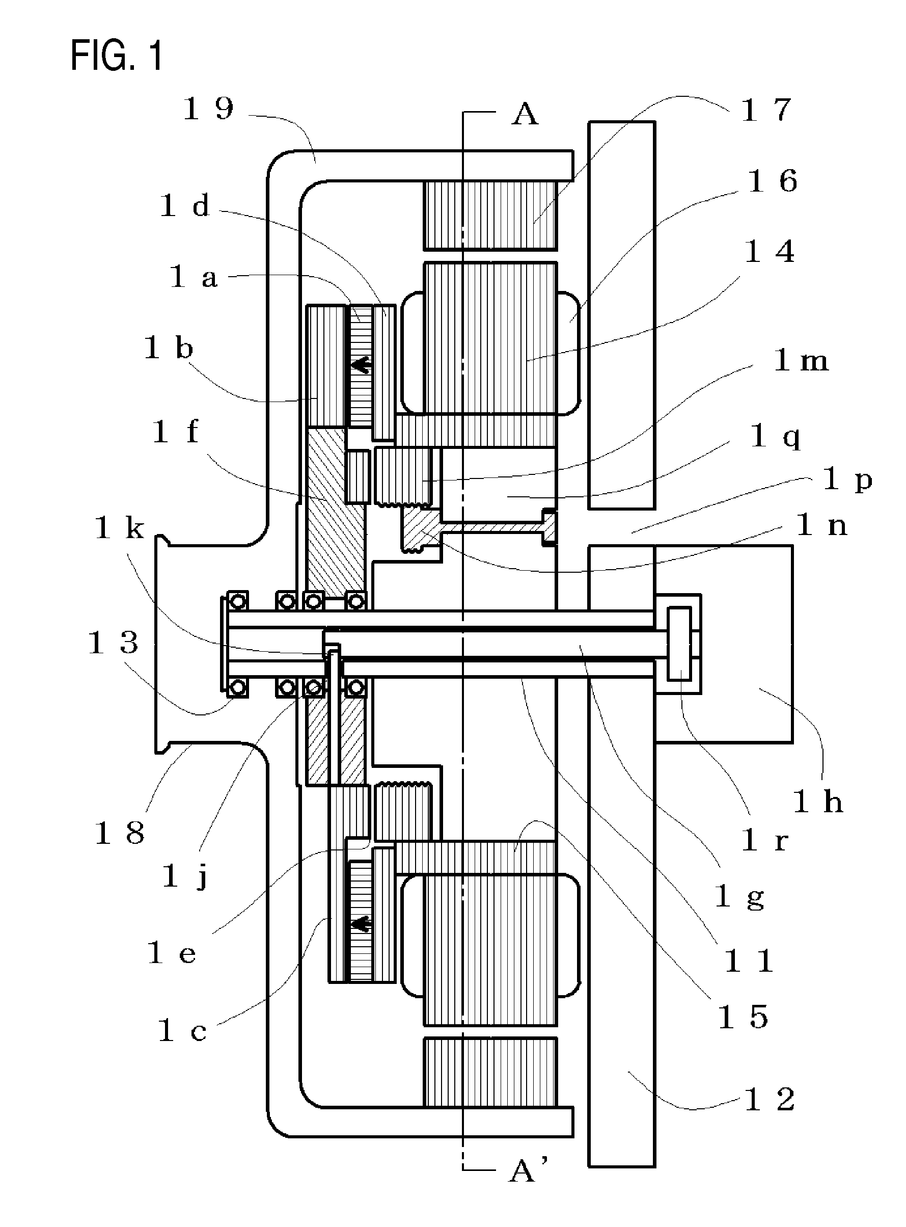
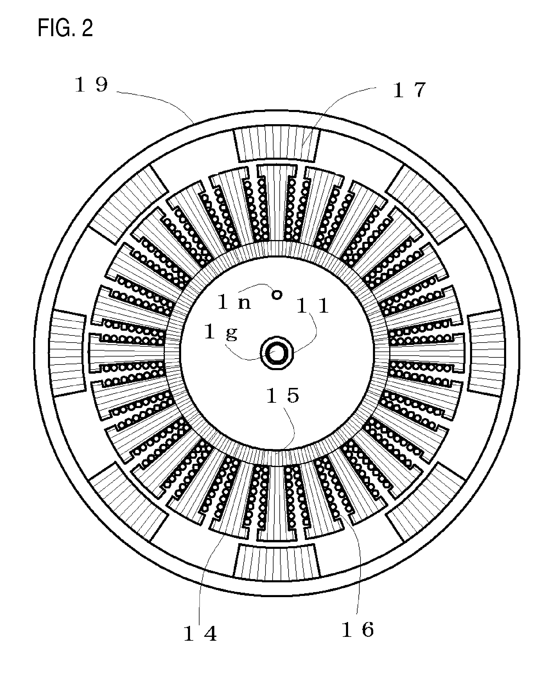
[0063]FIG. 2 shows a sectional view of the armature and the rotor along A-A′ of FIG. 1, and some of the component parts are appended with numbers for explaining the reciprocal relation. The armature is composed of the cylindrical magnetic yoke 15 fixed to the fixed shaft 11, a plurality of the magnetic teeth 14 having non-magnetic portions in the circumferential direction, and the armature coils 16 wound around the magnetic teeth 14. In the first embodiment, twenty four armature coils 16 are included and connected so as to have three phases. The magnetic teeth 14 and the cylindrical magnetic yokes 15 are composed by punching out a silicon steel plate by a predetermined die and then stacking the punched plates, and the armature coils 16 are wound.

[0064]In FIG. 2, in the rotor, eight magnetic salient poles 17 each in which silicon steel plates are stacked are disposed at even intervals in the circumferential direction. Spaces between the magnetic salient poles 17 are non-magnetic port...

second embodiment

[0112]FIG. 9 shows a sectional view of the armature and the rotor along the B-B′ in FIG. 8, and some component parts are appended with numbers for explaining the mutual relations. The armature includes the cylindrical magnetic yoke 85 fixed to the housing 82, a plurality of magnetic teeth 84 extending radially from the cylindrical magnetic yoke 85 and having non-magnetic portions in the circumferential direction, and the armature coils 86 wound around the magnetic teeth 84. The second embodiment includes nine armature coils 86, and three phases thereof are connected. In the edges of the magnetic teeth 84 of the armature, saturable magnetic junctions 93 that are short in the radial direction are provided between the contiguous edges of the magnetic teeth 84. The magnetic teeth 84 and the saturable magnetic junctions 93 are punched out of a silicon steel plate by a predetermined die and stacked and wound with the armature coils 86, and then, combined with the cylindrical magnetic yoke...

third embodiment

[0142]In FIG. 13, the rotor has a structure having the magnetic salient poles and the non-magnetic portions one after the other in the circumferential direction, and the adjacent magnetic salient poles are shown by numbers 131, 132, and the non-magnetic portions are shown by number 133. Number 134 shows a magnetic-flux channel portion. In this third embodiment, cross sectional area of the magnetic salient poles 131, 132 is not so large, then the magnetic-flux channel portion 134 that has wide cross sectional area exploiting the inside empty space is disposed. Therefore the enough amount of magnetic flux can flow in the magnetic-flux channel portion 134.

[0143]The magnetic salient poles 131, 132 that are conjugated by small width saturable magnetic junctions 135 are composed by punching out a silicon steel plate by a predetermined die and stacking the punched-out plates. The non-magnetic portion 133 between the magnetic salient poles 131, 132 is composed in non-magnetic resin or the l...


PUM


Abstract

In a magnet-exciting rotating electric machine, a magnetic excitation part for supplying a magnetic flux between a magnetic salient pole and an armature is composed to be divided into two so as to be capable of being relatively displaced. In this structure, the magnetic flux from the field magnet is divided into a main magnetic flux pathway that passes through the armature side and a bypass magnetic flux pathway that does not pass through the armature, and thereby, the magnetic flux of the main magnetic flux pathway is changed. The magnetic resistances of the main magnetic flux pathway and the bypass magnetic flux pathway are composed to be approximately equal, and then a magnetic force preventing the relative displacement is suppressed small. Thereby, the rotating electric machine system and the magnetic field control method in which magnetic field control is easy are provided.

Description

CROSS-REFERENCE TO RELATED APPLICATIONS[0001]The present application claims priority under 35 U.S.C. §119 to Japanese Patent Application Nos. 2007-212674 filed Aug. 17, 2007, 2007-279975 filed Oct. 29, 2007, and 2007-313140 filed Dec. 4, 2007. The contents of these applications are incorporated herein by reference in their entirety.BACKGROUND OF THE INVENTION[0002]1. Field of the Invention[0003]The present invention relates to rotating electric machines such as electric generators and electric motors having a permanent magnet.[0004]2. Description of the Related Art[0005]Rotating electric machine apparatuses, such as an electric generator for generating electric power electromagnetically by relative rotation between a permanent magnet and an armature, or an electric motor for generating relative rotation between a permanent magnet and an armature by interaction between the permanent magnet and a magnetic field generated by current supplied to the armature, are excellent in energy eff...

Claims


Application Information

Patent Timeline
IPC IPC(8): H02K21/00H02K3/18H02P9/00
CPCH02K1/274H02K21/24H02K21/14H02K7/125
Inventor ICHIYAMA, YOSHIKAZU
Owner KURA LAB
Why Eureka
Try Eureka