Field controllable rotating electric machine system with magnetic excitation part

a technology of magnetic excitation and rotating electric machines, which is applied in the direction of dynamo-electric converter control, motor/generator/converter stopper, magnetic circuit shape/form/construction, etc., can solve the problems of large energy loss, difficult control of the rotational speed range, and inability to obtain optimal power in a wide rotational speed range. , to achieve the effect of easy field weakening control

Inactive Publication Date: 2011-08-16
KURA LAB
View PDF25 Cites 11 Cited by
  • Summary
  • Abstract
  • Description
  • Claims
  • Application Information

AI Technical Summary

Benefits of technology

[0009]Accordingly, an embodiment of the present invention advantageously provides a method for controlling a magnetic flux amount, and a rotating electric machine system, by which field-weakening control becomes easy, while considering the following conditions: (1) there is little concern made to demagnetize a field magnet; (2) power required for an actuator in the magnetic flux amount control can be reasonable, and so forth.
[0012]This invention is further proposing, establishing magnetic resistances of the main magnetic flux path and the bypass magnetic flux path approximately equal each other as a minimum magnetic force condition. Then total amount of the magnetic flux which flows from the field magnet is maintained substantially constant, magnetic force preventing the movable magnetic pole part displacement can be maintained small, and precise magnetic flux amount control is made possible. The meaning which is “approximately equal” is to establish magnetic resistances thereof equally each other so that the magnetic force may be suppressed below power of an actuator used for the displacement.

Problems solved by technology

However, in both electric motors and electric generators, optimum power is not always obtained in a wide rotational speed range because of constant magnetic field strength from the field magnet.
In the case of the electric motor, the control thereof becomes difficult in a high-speed rotational region because the back electromotive force (power generation voltage) becomes too high, and therefore, various methods for weakening the field strength as field-weakening control have been proposed.
In the electric motor, field-weakening control by current phase control has been widely adopted, but energy loss is large because current flows that does not directly contribute to the rotation.
When current excitation for the control is used with a permanent magnet excitation, the structure of the rotating electric machine becomes complex and additionally energy loss is involved.
Furthermore, in the case of the electric generator, there has been a problem that cost of constant-voltage electronic circuit with a large electric power is large.
There is an advantage that the energy loss for the control is small because the relative displacement can be maintained mechanically, but there is a disadvantage that eddy-current loss is large in a high-speed rotational region because the amount of the magnetic flux flowing into the armature is constant.
A large force is required for the displacement control of the mechanism and vibration or hunting of the members is caused to make it difficult to perform the accurate control.
Furthermore, a large-power actuator, a control mechanism involving excessive mechanical strength, and so forth are required, and therefore, realization of the apparatus involves difficulty.

Method used


Image

  • Field controllable rotating electric machine system with magnetic excitation part
  • Field controllable rotating electric machine system with magnetic excitation part
  • Field controllable rotating electric machine system with magnetic excitation part

Examples


first embodiment

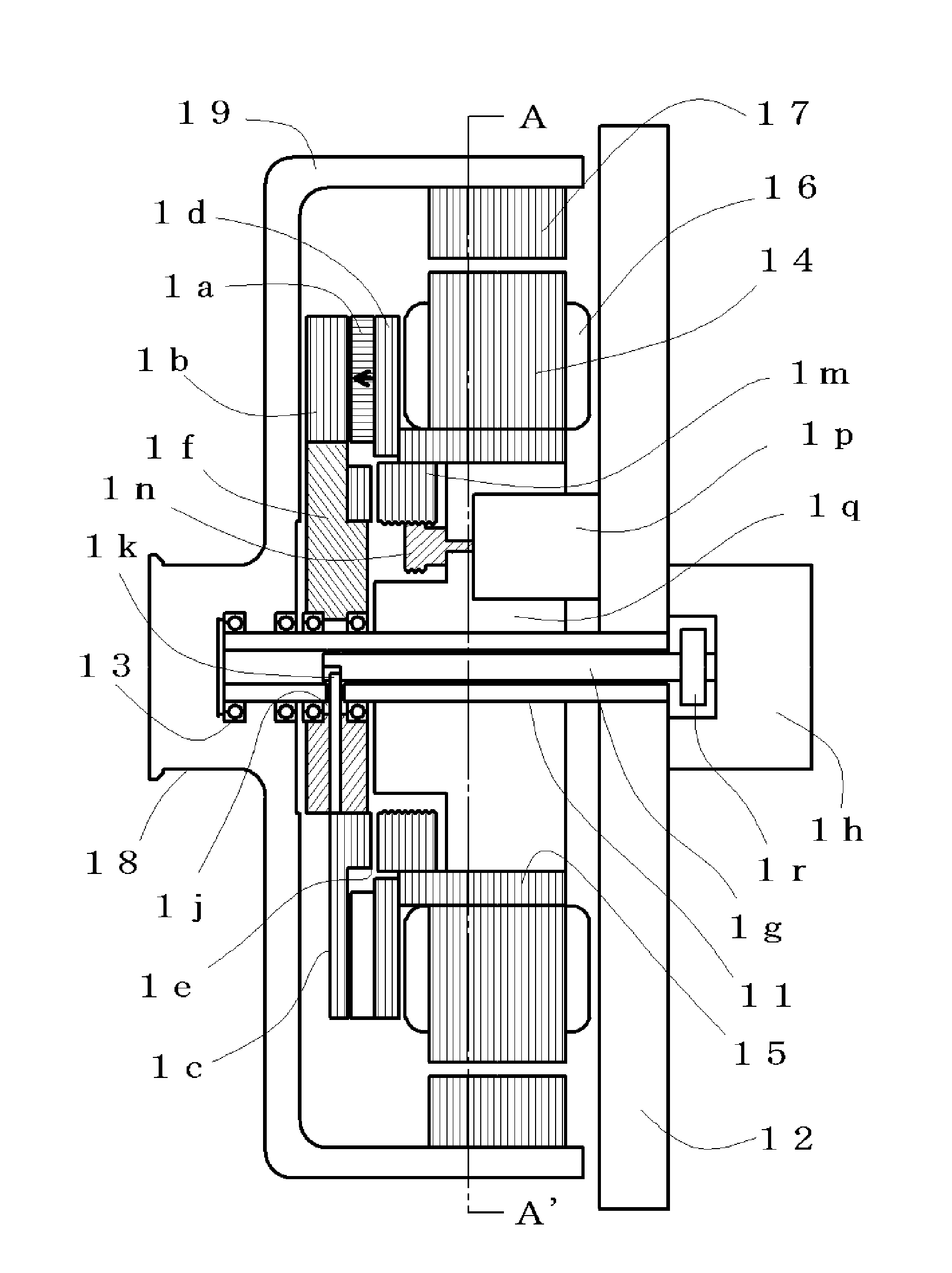
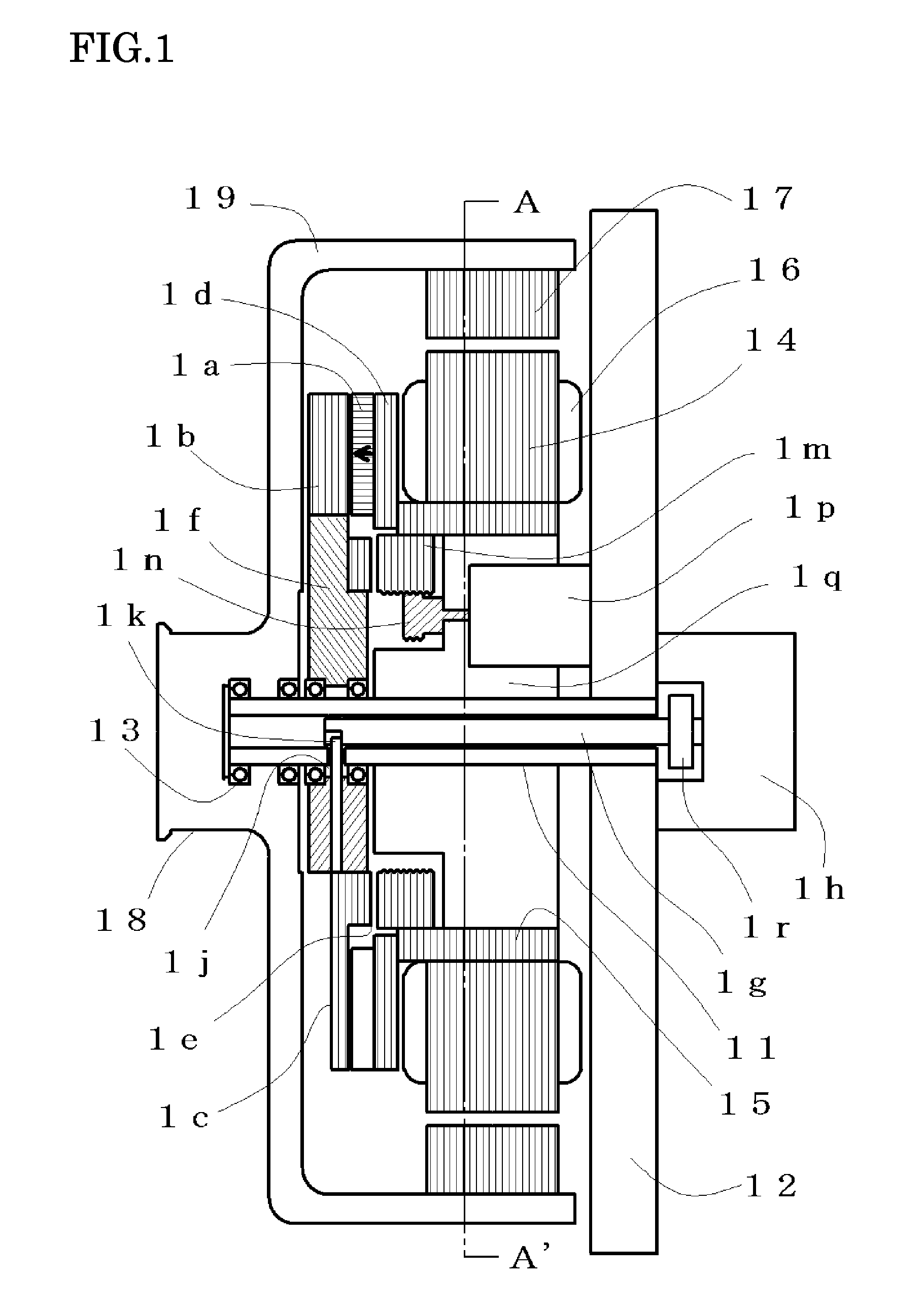
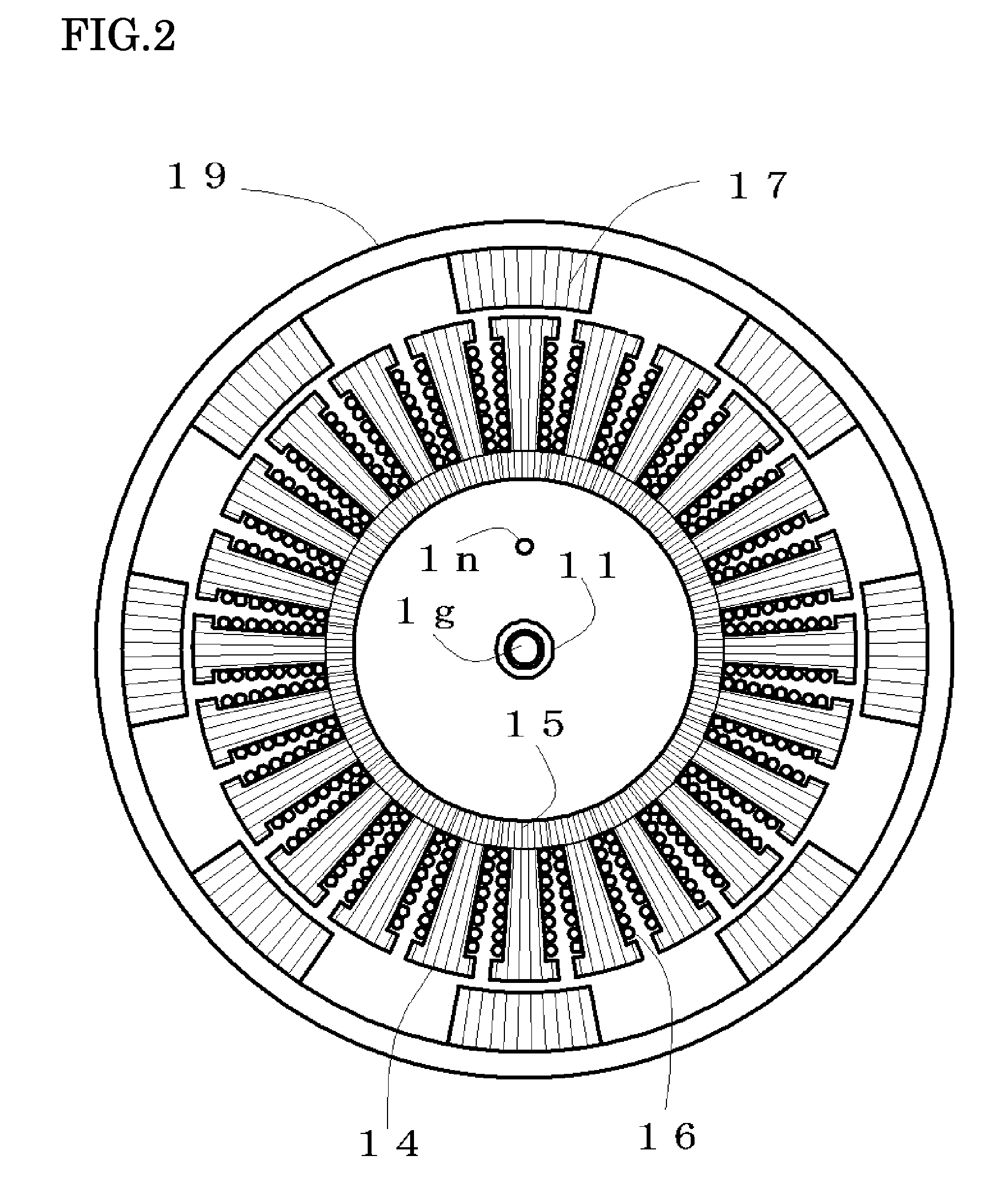
[0055]FIG. 2 illustrates a sectional view of the armature and the rotor along A-A′ of FIG. 1, and some of component parts are appended with numbers for explaining the reciprocal relation. The armature is composed of the cylindrical magnetic yoke 15 fixed to the armature support 1q, a plurality of the magnetic teeth 14 having non-magnetic portions in the circumferential direction, and the armature coils 16 wound around the magnetic teeth 14. In the first embodiment, twenty four armature coils 16 are included and connected so as to have three phases. The magnetic teeth 14 and the cylindrical magnetic yokes 15 are composed by punching out a silicon steel plate by a predetermined die and then stacking the punched plates, and the armature coils 16 are wound.

[0056]In FIG. 2, in the rotor, eight magnetic salient poles 17 each in which silicon steel plates are stacked are disposed at even intervals in the circumferential direction. Spaces between the magnetic salient poles 17 are non-magnet...

second embodiment

[0093]As described above, in the rotating electric machine apparatus shown in FIGS. 7 to 10, it has been explained that by relatively displacing the field magnet 7a with respect to the main magnetic pole 7b and the bypass magnetic pole 7c, an amount of the magnetic flux flowing through the armature can be controlled, and furthermore, the means and the method for displacing the field magnet 7a with respect to the main magnetic pole 7b and the bypass magnetic pole 7c have been explained. The second embodiment is a system for optimizing the output by controlling the magnetic flux amount, and the control method as the rotating electric machine system will be explained by using FIG. 6.

[0094]A rotating electric machine system in which the rotating electric machine apparatus is used as an electric motor and by which the field-weakening control is performed to optimize the rotational force control will be explained. When the rotational speed that is the output 63 becomes larger than a prede...

third embodiment

[0117]As described above, in the rotating electric machine apparatus shown in FIGS. 11 to 15, it has been explained that by relatively displacing the field magnet 114 with respect to the main magnetic pole 115 and the bypass magnetic pole 116, an amount of the magnetic flux flowing through the armature can be controlled. The third embodiment is a system for optimizing the output by controlling the magnetic flux amount, and the control method as the rotating electric machine system will be explained by using FIG. 6.

[0118]A rotating electric machine system in which the rotating electric machine apparatus is used as an electric motor and by which the field-weakening control is performed to optimize the rotational force control will be explained. When the rotational speed that is the output 63 becomes larger than a predetermined value and an amount of the magnetic flux flowing through the armature is made to be smaller, the control device 65 supplies the minimum magnetic force current t...


PUM


Abstract

In a magnet-exciting rotating electric machine system, every magnetic salient pole group to be magnetized in a same polarity is collectively magnetized by a magnetic excitation part. In the magnetic excitation part, a main magnetic flux path in which a magnetic flux circulates through the armature and a bypass magnetic flux path are connected to the field magnet in parallel. Magnetic flux amount in each path is controlled by mechanical displacement. Thereby, the rotating electric machine system and the magnetic flux amount control method in which magnetic field control is easy are provided. Also, means and method are provided so that a power required for the displacement may be made small by adjusting magnetic resistance of the above magnetic flux path.

Description

CROSS-REFERENCE TO RELATED APPLICATIONS[0001]The present application is a continuation-in-part of U.S. patent application Ser. No. 12 / 024,911, filed Feb. 1, 2008, and claims priority under 35 U.S.C. §119 to Japanese Patent Application Nos. 2007-212674 filed Aug. 17, 2007, 2007-279975 filed Oct. 29, 2007, 2007-313140 filed Dec. 4, 2007, 2008-13500 filed Jan. 24, 2008, 2008-74809 filed Mar. 24, 2008 and 2008-116918 filed Apr. 28, 2008. The contents of these applications are incorporated herein by reference in their entirety.BACKGROUND OF THE INVENTION[0002]1. Field of the Invention[0003]The present invention relates to rotating electric machines such as electric generators and electric motors having a permanent magnet.[0004]2. Description of the Related Art[0005]Rotating electric machine apparatuses, such as an electric generator for generating electric power electromagnetically by relative rotation between a permanent magnet and an armature, or an electric motor for generating relati...

Claims


Application Information

Patent Timeline
Patent Type & Authority Patents(United States)
IPC IPC(8): H02K21/16H02K1/27H02K1/22H02K16/02H02K21/12H02P9/14
CPCH02K11/048H02K21/028H02K21/02
Inventor ICHIYAMA, YOSHIKAZU
Owner KURA LAB
Why Eureka
Try Eureka