Field controllable rotating electric machine system with magnetic excitation part
a technology of magnetic excitation and rotating electric machines, which is applied in the direction of dynamo-electric converter control, motor/generator/converter stopper, magnetic circuit shape/form/construction, etc., can solve the problems of large energy loss, difficult control of the rotational speed range, and inability to obtain optimal power in a wide rotational speed range. , to achieve the effect of easy field weakening control
- Summary
- Abstract
- Description
- Claims
- Application Information
AI Technical Summary
Benefits of technology
Problems solved by technology
Method used
Image
Examples
first embodiment
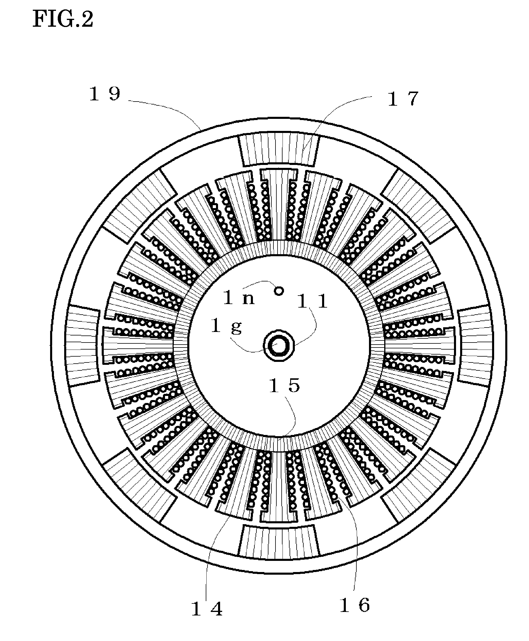
[0055]FIG. 2 illustrates a sectional view of the armature and the rotor along A-A′ of FIG. 1, and some of component parts are appended with numbers for explaining the reciprocal relation. The armature is composed of the cylindrical magnetic yoke 15 fixed to the armature support 1q, a plurality of the magnetic teeth 14 having non-magnetic portions in the circumferential direction, and the armature coils 16 wound around the magnetic teeth 14. In the first embodiment, twenty four armature coils 16 are included and connected so as to have three phases. The magnetic teeth 14 and the cylindrical magnetic yokes 15 are composed by punching out a silicon steel plate by a predetermined die and then stacking the punched plates, and the armature coils 16 are wound.
[0056]In FIG. 2, in the rotor, eight magnetic salient poles 17 each in which silicon steel plates are stacked are disposed at even intervals in the circumferential direction. Spaces between the magnetic salient poles 17 are non-magnet...
second embodiment
[0093]As described above, in the rotating electric machine apparatus shown in FIGS. 7 to 10, it has been explained that by relatively displacing the field magnet 7a with respect to the main magnetic pole 7b and the bypass magnetic pole 7c, an amount of the magnetic flux flowing through the armature can be controlled, and furthermore, the means and the method for displacing the field magnet 7a with respect to the main magnetic pole 7b and the bypass magnetic pole 7c have been explained. The second embodiment is a system for optimizing the output by controlling the magnetic flux amount, and the control method as the rotating electric machine system will be explained by using FIG. 6.
[0094]A rotating electric machine system in which the rotating electric machine apparatus is used as an electric motor and by which the field-weakening control is performed to optimize the rotational force control will be explained. When the rotational speed that is the output 63 becomes larger than a prede...
third embodiment
[0117]As described above, in the rotating electric machine apparatus shown in FIGS. 11 to 15, it has been explained that by relatively displacing the field magnet 114 with respect to the main magnetic pole 115 and the bypass magnetic pole 116, an amount of the magnetic flux flowing through the armature can be controlled. The third embodiment is a system for optimizing the output by controlling the magnetic flux amount, and the control method as the rotating electric machine system will be explained by using FIG. 6.
[0118]A rotating electric machine system in which the rotating electric machine apparatus is used as an electric motor and by which the field-weakening control is performed to optimize the rotational force control will be explained. When the rotational speed that is the output 63 becomes larger than a predetermined value and an amount of the magnetic flux flowing through the armature is made to be smaller, the control device 65 supplies the minimum magnetic force current t...
PUM
 Abstract
Description
Claims
Application Information
 - R&D
- Intellectual Property
- Life Sciences
- Materials
- Tech Scout
- Unparalleled Data Quality
- Higher Quality Content
- 60% Fewer Hallucinations
Browse by: Latest US Patents, China's latest patents, Technical Efficacy Thesaurus, Application Domain, Technology Topic, Popular Technical Reports.
© 2025 PatSnap. All rights reserved.Legal|Privacy policy|Modern Slavery Act Transparency Statement|Sitemap|About US| Contact US: help@patsnap.com


