
Augmented Rack And Pinion Steering System

Pending Publication Date: 2022-06-09
BANDY RONALD S
View PDF0 Cites 0 Cited by
  • Summary
  • Abstract
  • Description
  • Claims
  • Application Information

AI Technical Summary

Benefits of technology

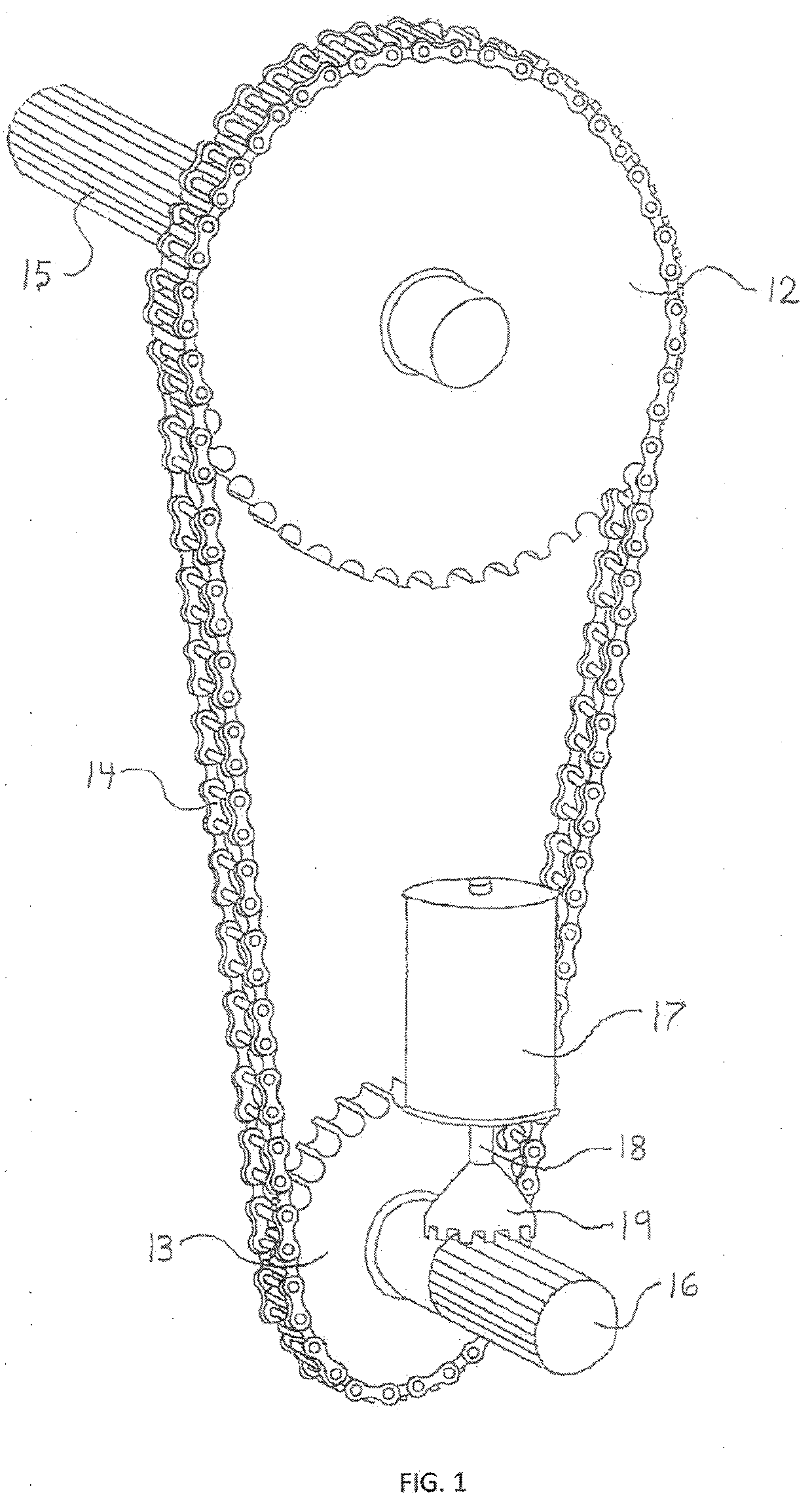
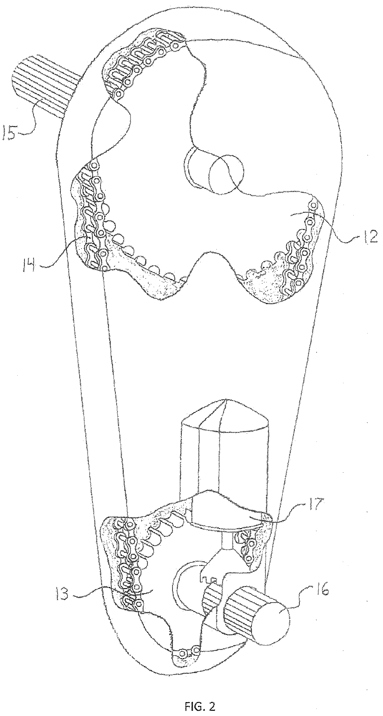
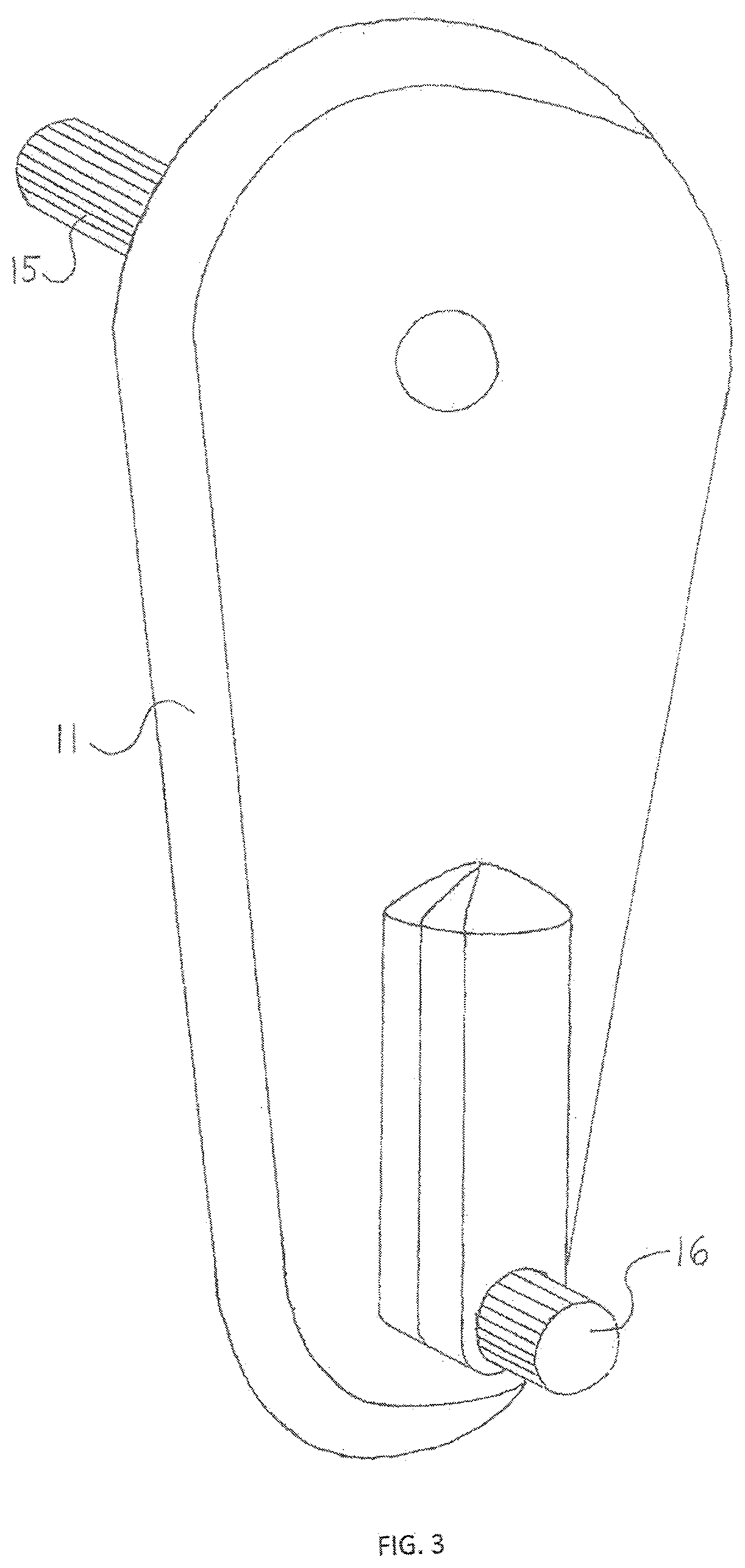
The patent describes a steering system for vehicles that includes a manual rack and pinion gearset, an augmented chain and sprocket assembly, an electric assist motor box, and associated linkages. The system has a slow steering ratio and an electric motor that doubles the steering input. The electric assist motor is located away from the gearset to remove the motor from the front axle and preserve precise steering response during adverse driving conditions. The system allows for effortless rotation of the output shaft and results in a small turn of the front wheels. The technical effects of the system include improved steering response, reduced bumpsteer, and improved vehicle control.

Problems solved by technology

The slow steering ratio means that for a small rotation of the pinion shaft, the displacement of the rack is very small.
This way, a small rotation of the pinion shaft causes a very small displacement of the rack, which leads to a very small turn of the front wheels.
The small simulated rotation of the pinion shaft is reduced by the slow steering ratio and thereby causes a very small unintended displacement of the rack, which leads to a very small unintended turn of the front wheels.
The multiplied rotation of the pinion shaft causes an increased displacement of the rack, which leads to an increased turn of the front wheels.
The augmented chain and sprocket assembly has input and output shafts whereby the augmentation makes the rotation of the output shaft by the input shaft more difficult.

Method used


Image

  • Augmented Rack And Pinion Steering System
  • Augmented Rack And Pinion Steering System
  • Augmented Rack And Pinion Steering System

Examples


Embodiment Construction

[0046]The present invention represents a steering system designed to function with a vehicle whose frame is suspended above front and rear solid or beam type axles, the front axle being steerable. The steering system utilizes mechanical linkages and is specifically designed to operate in conjunction with a triangulated link-style suspension system.

[0047]For discussion purposes: One, only the front portion of a chassis is shown in the drawings, and includes part of the driver and passenger frame sides, front end of the frame, and firewall 10. Two, the front suspension system is not shown in the drawings. While a front solid axle is disposed beneath the chassis as appropriate, the axle is not connected to the chassis via suspension control links. Three, the electric motor 17 that is able to be oriented adjacent to either the input shaft 15 or output shaft 16 of the augmented chain and sprocket assembly 11 is oriented adjacent to the output shaft 16 only. Four, maximum articulation of ...


PUM


Abstract

The present invention is a steering system for a beam-type solid axle arrangement. The steering system is designed to operate in conjunction with the triangulated link-style suspension system with zero bumpsteer during suspension travel and negligible bumpsteer during articulation. Accurate steering throughout suspension operations is satisfied with mechanical linkages that include a slow ratio rack and pinion gearset and unique augmented chain and sprocket assembly. The slow ratio of the rack and pinion gearset ensures negligible bumpsteer during articulation, thereby leading to negligible if any bumpsteer throughout operation of the suspension system. Meanwhile, augmentation of the chain and sprocket assembly defines a steering quickener effect thereby speeding up the rack and pinion gearset and restoring quick steering response. Effortless steering is ensured by appropriate use of electric or hydraulic assist devices.

Description

CROSS-REFERENCE TO RELATED APPLICATIONS[0001]This application represents a steering system specifically designed to operate in conjunction with a vehicle equipped with a front solid or beam axle and triangulated link-style suspension system.STATEMENT REGARDING FEDERALLY SPONSORED RESEARCH OR DEVELOPMENT[0002]Not ApplicableREFERENCE TO SEQUENCE LISTING, A TABLE, OR A COMPUTER PROGRAM LISTING COMPACT DISC APPENDIX[0003]Not ApplicableBACKGROUND OF THE INVENTION[0004]The triangulated 4-link suspension system is the preferred front suspension system for a front solid axle four-wheel drive vehicle. A survey of the winningest, most competitive front solid axle four-wheel drive race vehicles quickly reveals that the front suspension system is based on the triangulated 4-link configuration. Despite such storied success in the off-road environment, the triangulated 4-link front (or rear) suspension system is not offered as a production-based or even as an optional performance-based suspension...

Claims


Application Information

Patent Timeline
IPC IPC(8): B62D3/12F16H7/06F16H57/00F16H57/035B62D1/04B62D1/16B62D5/04B62D7/16B62D7/18
CPCB62D3/12F16H7/06F16H57/0025F16H57/035F16H2057/02034B62D1/16B62D5/0403B62D7/166B62D7/18B62D1/04B62D7/08B62D5/0409B62D5/22B62D1/163B62D5/04
Inventor BANDY, RONALD S.
Owner BANDY RONALD S
Learn More