Large aperture antenna with narrow angle fast beam steering

Active Publication Date: 2013-12-05
ELBIT SYST LTD
View PDF8 Cites 36 Cited by
  • Summary
  • Abstract
  • Description
  • Claims
  • Application Information

AI Technical Summary

Benefits of technology

[0009]The present invention, in embodiments thereof, provides a system for rapidly steering a directive beam in an antenna. The system includes: an antenna configured to produce a directive beam; means for steering the beam rapidly, along small angles; and means for steering the beam slowly, along large angles. According to one embodiment, the antenna is implemented as a phased array antenna, wherein the means for steering the beam rapidly, along small angles, is impleme

Problems solved by technology

Fast beam movements of a mechanically steered antenna, even if the motions are small, requires large mechanical moments which means sturdy motors and mechanics, large currents and high power electronics.
Phased arrays do not require all of these but have other drawbacks—their di

Method used


Image

  • Large aperture antenna with narrow angle fast beam steering
  • Large aperture antenna with narrow angle fast beam steering
  • Large aperture antenna with narrow angle fast beam steering

Examples


Embodiment Construction

[0016]Before explaining at least one embodiment of the invention in detail, it is to be understood that the invention is not limited in its application to the details of construction and the arrangement of the components set forth in the following description or illustrated in the drawings. The invention is applicable to other embodiments or of being practiced or carried out in various ways. Also, it is to be understood that the phraseology and terminology employed herein is for the purpose of description and should not be regarded as limiting.

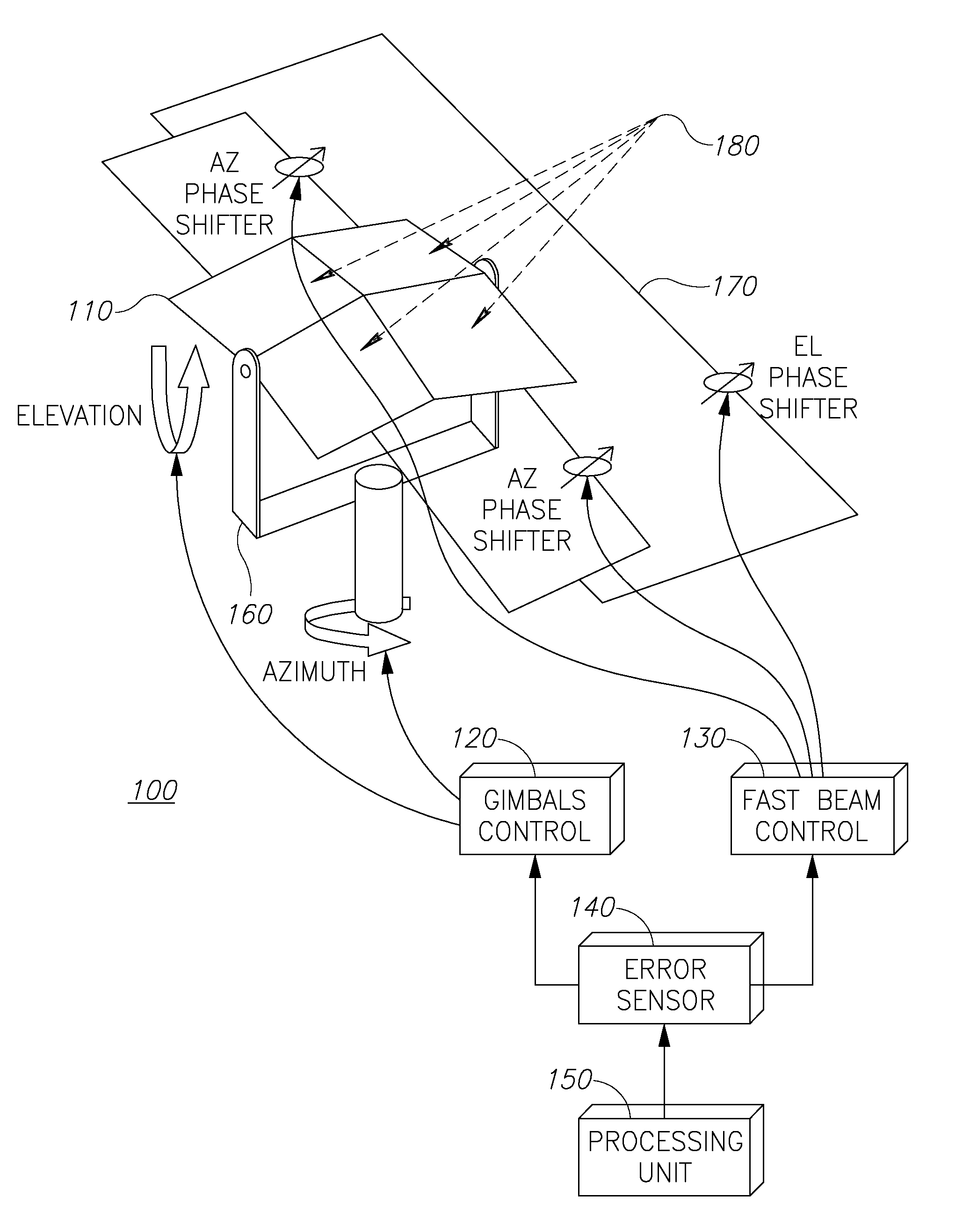
[0017]Embodiments of the present invention provide a system for steering an antenna both in short-fast movements and in long-slow movements, possibly but not exclusively, implemented as an antenna of a mobile SATCOM terminal. The dimensions of this antenna are determined by the SATCOM link budget and by SATCOM regulations. For example, to provide reasonable data rates and conform to these regulations, the antenna would have an aperture of 60 c...


PUM


Abstract

A system for rapidly steering a directive beam in an antenna is provided herein. The system includes: an antenna configured to produce a directive beam; means for steering the beam rapidly, along small angles; and means for steering the beam slowly, along large angles. According to one embodiment, the antenna is implemented as a phased array antenna, wherein the means for steering the beam rapidly, along small angles, is implemented as a phased array control, and wherein the means for steering the beam slowly, along large angles, is a mechanical mechanism implemented using gimbals. According to another embodiment, the antenna includes a main reflector and a sub reflector, and wherein the means for steering the beam rapidly, along small angles, mechanically controls the sub reflector, and wherein the means for steering the beam slowly, along large angles, mechanically controls the main reflector.

Description

BACKGROUND[0001]1. Technical Field[0002]The present invention relates to the field of antennas, and more particularly, to systems for rapidly steering antennas having directive beams.[0003]2. Discussion of Related Art[0004]Two main technologies are known in the art for implementing a telecommunication antenna (such as Satellite Communication—SATCOM) on a mobile platform (such as an Unmanned Arial Vehicles—UAVs). Such an antenna needs to address both short and fast movements as well as long and relatively slow movements.[0005]One known technology is a mechanically steered antenna. An antenna (e.g.—a parabolic dish) is mounted on a motorized 3 axis gimbals. The motors are controlled to implement the fast and slow movements of the dish.[0006]Another technology is phased array in which the antenna comprises of a large number of small—i.e.—Omni directional—radiating elements, the phase and sometime amplitude of the signals of each element is controlled so that the signals going through a...

Claims


Application Information

Patent Timeline
IPC IPC(8): H01Q3/08H01Q3/26H01Q3/20
CPCH01Q3/08H01Q3/20H01Q3/26H01Q19/175
Inventor ZAHAVI, DOVLAUFER, SHAUL BARUCH
Owner ELBIT SYST LTD
Why Eureka
Try Eureka