Ink jet printing apparatus, dummy jet method, and program
- Summary
- Abstract
- Description
- Claims
- Application Information
AI Technical Summary
Benefits of technology
Problems solved by technology
Method used
Image
Examples
first embodiment
[0150][Dummy Jet Method ]
[0151]FIG. 9 is a flowchart illustrating a procedure of a dummy jet method according to a first embodiment. In the dummy jet method according to the first embodiment, the necessity of the execution of the dummy jet is determined in consideration of the next jetting.
[0152]A dummy jet reset step S100 illustrated in FIG. 9 corresponds to the dummy jet reset step S10 illustrated in FIG. 6. Similarly, a jetting amount update step S102 illustrated in FIG. 9 corresponds to the jetting amount update step S12 illustrated in FIG. 6. Here, the detailed description is omitted.
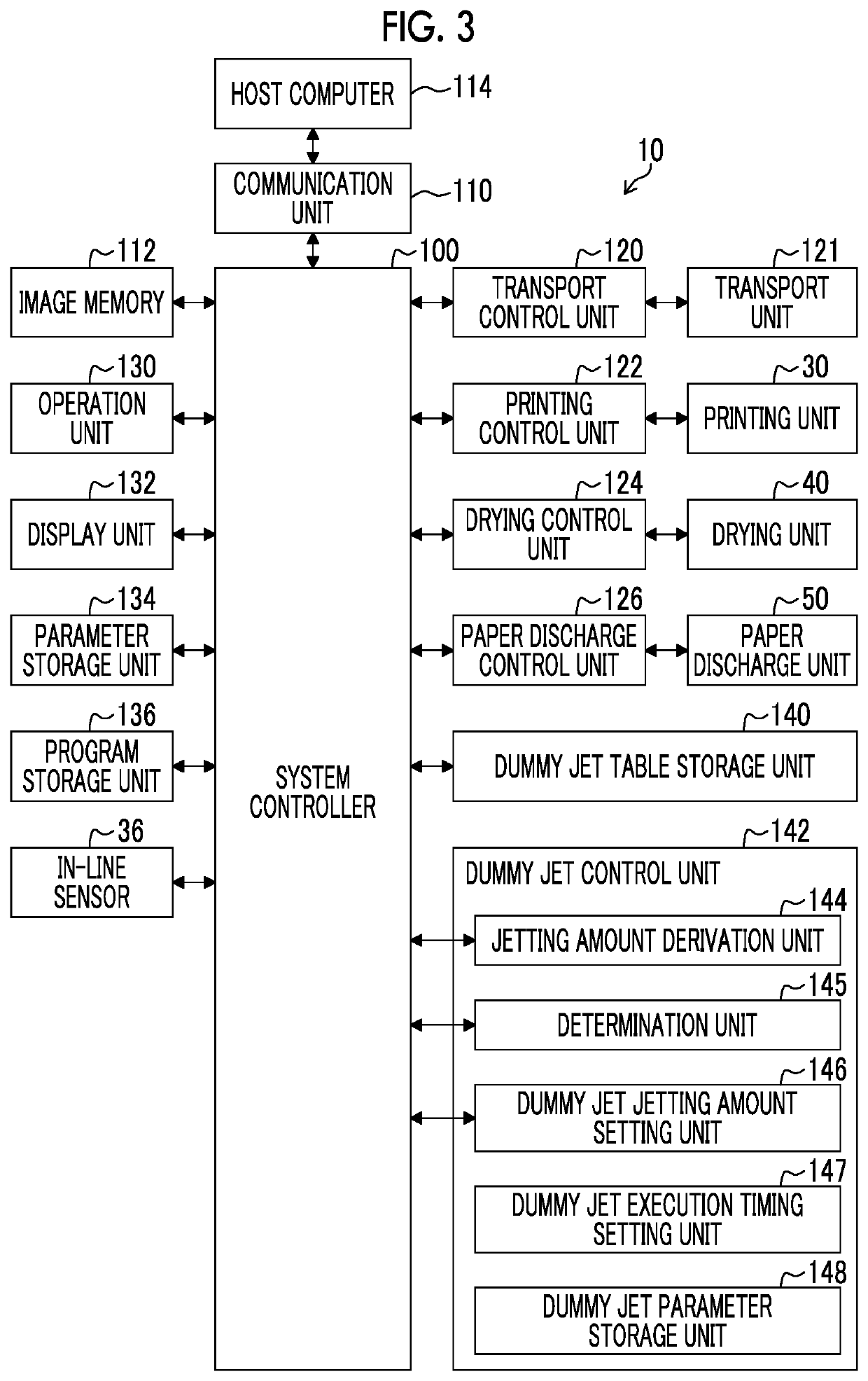
[0153]In a timing update step S104, the dummy jet control unit 142 illustrated in FIG. 3 updates the time t and a printing elapsed period t_total. The printing elapsed period t_total is an elapsed period using the printing start as a start timing.
[0154]Specifically, the dummy jet control unit 142 sets time t=t+1 and printing elapsed period t_total=t_total+1. After the timing update step S104, the p...
second embodiment
[0173][Dummy Jet Method ]
[0174]FIG. 10 is a flowchart illustrating a procedure of a dummy jet method according to a second embodiment. The form in which the execution timing of the dummy jet is changed illustrated in FIG. 7 is applied to the dummy jet method according to the second embodiment.
[0175]A dummy jet timing setting step S130, a dummy jet jetting amount setting step S132, a timing reset step S134, a timing update step S136, and a dummy jet execution timing determination step S138 illustrated in FIG. 10 correspond to the dummy jet timing setting step S30 to the dummy jet execution timing determination step S38 illustrated in FIG. 8, respectively.
[0176]In the dummy jet execution timing determination step S138, in a case where the determination unit 145 illustrated in FIG. 3 determines that the time t is not the dummy jet execution timing t_dj_i, a No determination is made. In a case of the No determination, the processing proceeds to a printing step S142.
[0177]On the other ha...
application example
[0214][Application Example to Program]
[0215]A program corresponding to the ink jet printing apparatus 10 and the dummy jet method disclosed in the present specification can be configured. That is, the present specification discloses a program causing a computer to execute a dummy jet condition setting function of setting a non-jettable period and a required jetting amount of the ink jet head, for each nozzle; and a dummy jet function of executing a dummy jet for a dummy jet execution nozzle with a jetting amount insufficient for the required jetting amount, in which, at a determination timing, for the nozzle of which a total jetting amount in the non-jettable period is less than the required jetting amount, the dummy jet function executes a dummy jet in a case where a period from a printing start to a next jetting timing is less than a period obtained by adding a determination interval to a period from the printing start to the determination timing, and does not execute a dummy jet ...
PUM
 Abstract
Description
Claims
Application Information
 - R&D
- Intellectual Property
- Life Sciences
- Materials
- Tech Scout
- Unparalleled Data Quality
- Higher Quality Content
- 60% Fewer Hallucinations
Browse by: Latest US Patents, China's latest patents, Technical Efficacy Thesaurus, Application Domain, Technology Topic, Popular Technical Reports.
© 2025 PatSnap. All rights reserved.Legal|Privacy policy|Modern Slavery Act Transparency Statement|Sitemap|About US| Contact US: help@patsnap.com


