Bending and shifting system for rolling mill stands

a technology of shifting system and rolling mill stand, which is applied in the direction of metal rolling arrangement, counter-pressure device, manufacturing tools, etc., can solve the problems of increasing the number of spare shifting block to be set up, etc., and achieves the effect of increasing the management cost of the stand and being easy to manage and manipula

Active Publication Date: 2022-04-21
DANIELI & C OFF MEC SPA
View PDF6 Cites 2 Cited by
  • Summary
  • Abstract
  • Description
  • Claims
  • Application Information

AI Technical Summary

Benefits of technology

[0014]The bending and shifting system of the rolling rolls present in the rolling mill stand of the invention, by virtue of such features, is more easily manageable and manipulable since the upper bending block is supported and controlled in the lifting and lowering movements thereof by the upper backing roll chock itself which, in the event of the complete replacement thereof together with the work roll and the backing roll, does not also require the disassembly of the balancing crosspiece which may remain in the place thereof in the stand.
[0015]Furthermore, by virtue of the fixing of the shifting block on the bending block instead of directly on the chock of the work roll or on the housing of the stand, there is the advantage that also the shifting block is fixed on an element which is integral with the stand and, when the stand work rolls replacement operation occurs, it does not need to be detached from the housing or from an element which remains attached to the housing. This avoids having additional sets of shifting blocks to be managed outside of the stand together with the work rolls, which would entail an increase in the number of spare shifting blocks to be set up in the rolling plant and an increase in the management costs of the stand.
[0016]A further advantage of the invention derives from the sliding fixing of the bending block in the lateral guides with a T-section, which allow the chock of the work and backing rolls to move in a vertical direction, and at the same time avoid the detachment of the bending block from the housing of the rolling mill stand when the work roll and / or the backing roll are replaced.

Problems solved by technology

This avoids having additional sets of shifting blocks to be managed outside of the stand together with the work rolls, which would entail an increase in the number of spare shifting blocks to be set up in the rolling plant and an increase in the management costs of the stand.

Method used


Image

  • Bending and shifting system for rolling mill stands
  • Bending and shifting system for rolling mill stands
  • Bending and shifting system for rolling mill stands

Examples


Embodiment Construction

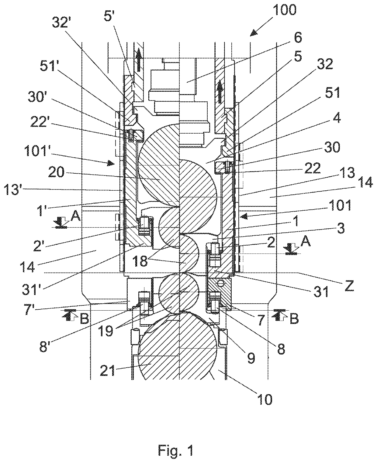
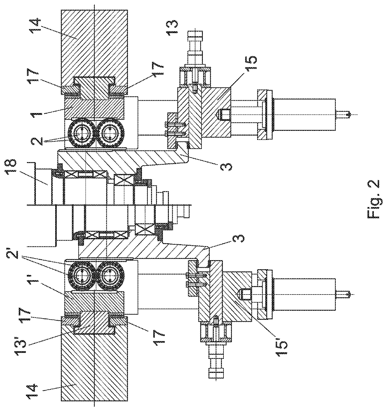
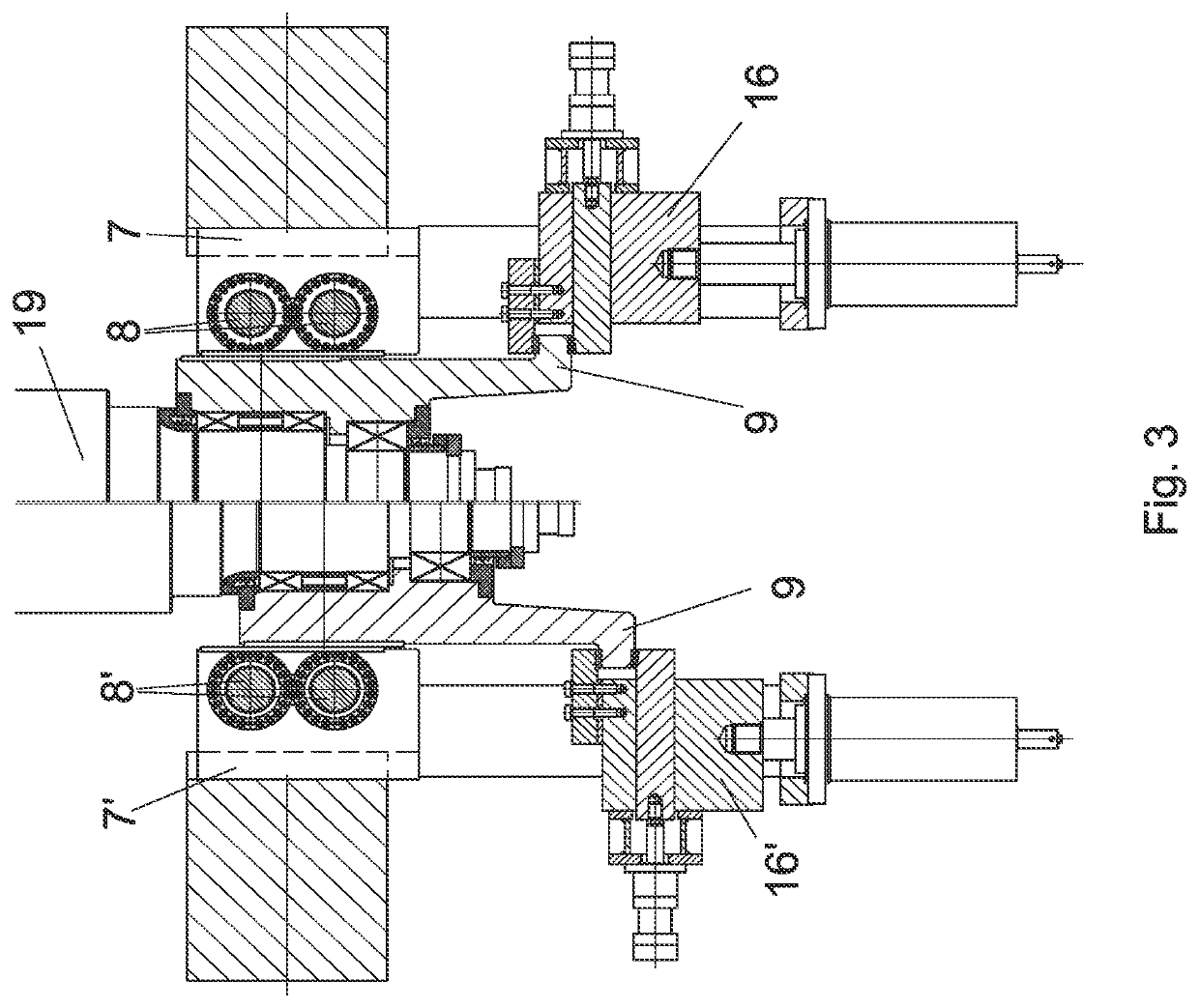
[0024]With reference to the Figures, a rolling mill stand, which is arranged transversely with respect to the rolling direction Z, has been generally indicated with reference numeral 100. The rolling mill stand is of the quadruple type with two work rolls, the upper work roll 18 and the lower work roll 19, and is provided with two backing rolls: the upper one 20 and the lower one 21, of a diameter greater with respect to the one of the work rolls. With reference to FIG. 1, FIG. 2 and FIG. 3, in the description, exclusively for convenience of explanation, reference is made to a single side of the rolling mill stand 100, the one facing the operator. The part of the stand which is not shown in the Figures of the motor part is made up of similar elements, except for the absence, in particular, of the shifting elements, and provided that in the following description it is not otherwise and expressly specified.

[0025]The rolling mill stand 100 has two housings of which only the housing 14 ...


PUM

PropertyMeasurementUnit
thicknessaaaaaaaaaa
distanceaaaaaaaaaa
thicknessaaaaaaaaaa

Abstract

The rolling mill stand comprises a bending device and a shifting device for the rolling rolls. The housing supports the upper backing and work rolls, and the lower backing and work roll and comprises the lower bending block, the upper bending block, the chock of the upper work roll, the chock of the lower work roll, the axial shifting device of the upper work roll, the axial shifting device of the lower work roll. The chock of the lower work roll is coupled with the lower bending block to transmit a bending load on the lower work roll. The upper bending block transmits a bending load on the upper work roll by means of the action of actuators. The bending block comprises a slide with a T-section which slides in the guide and a chock of the upper backing roll, whereby the upper bending block, instead of being a single piece, is formed by two different and separate structural components.

Description

CROSS-REFERENCE TO RELATED APPLICATIONS[0001]This application claims priority to PCT International Application No. PCT / IB2020 / 050363 filed on Jan. 17, 2020, which application claims priority to Italian Patent Application No. 102019000000713 filed on Jan. 17, 2019, the disclosures of which are expressly incorporated herein by reference.STATEMENT RE: FEDERALLY SPONSORED RESEARCH / DEVELOPMENT[0002]Not applicable.BACKGROUND OF THE INVENTIONField of the Invention[0003]The present invention relates to the field of rolling plane metal products, in particular, to rolling mill stands.Background Art[0004]Rolling mill stands for rolling flat products, for example sheet metal, having combined systems are known which allow the translation of work rolls under load, i.e. shifting, while, at the same time, the straightening (or bending) load is applied to the chocks of the work rolls, even in case a large opening must be ensured between the work rolls in a rolling mill stand. In particular, in rolli...

Claims


Application Information

Patent Timeline
Patent Type & Authority Applications(United States)
IPC IPC(8): B21B31/22
CPCB21B31/22B21B31/18B21B2013/025B21B29/00
Inventor DORIGO, ANDREA
Owner DANIELI & C OFF MEC SPA
Why Eureka
Try Eureka