Differential gravity power generator

Inactive Publication Date: 2022-05-12
EMID SOEMAR
View PDF0 Cites 0 Cited by
  • Summary
  • Abstract
  • Description
  • Claims
  • Application Information

AI Technical Summary

Problems solved by technology

Furthermore, the water in the box is not a conservative system, as it is in interaction with the earth through the gravity.
Comment: Even if it works th

Method used


Image

  • Differential gravity power generator

Examples


Example

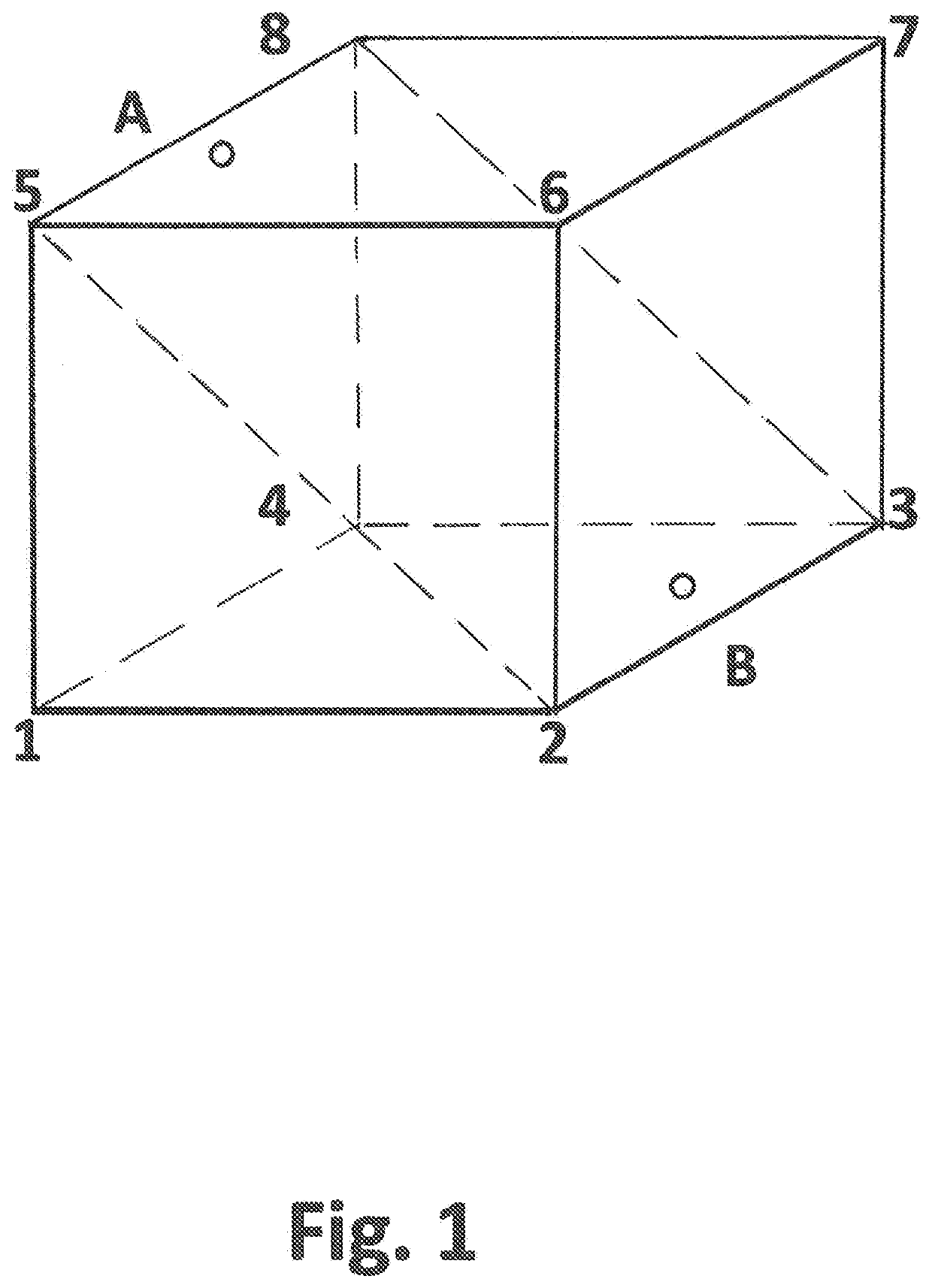
[0011]FIG. 1. A box, divided into T1(1, 2, 3, 4, 5, 8) and T2(2, 3, 5, 6, 7, 8) by plane (2, 3, 5, 8) with openings A above and B below. Height H is distance 1-5, length L is distance 1-2 and width W is distance 1-4. The box is filled with an incompressible fluid and is subject to gravity. The difference in effective head of T2 over T1 is % H, resulting in a cyclic fluid motion from T2 to T1 through B and from T1 to T2 through A.

PREFERRED APPLICATIONS

[0012]1. T1T2—Model as in FIG. 1 and Other Configurations.

Second example. The rectangular box is of glass (aquarium), with L=W=0.3 m, H=0.4 m, slanted plane of concrete casing 0.3×0.58 m. B: Ø 22 mm, A: Ø 12 mm. The initial flow is about 1 cm / s during 45 minutes. The long time evolution of the flow is between 2-8 mm / s with diurnal variation, experimental duration was one week.

Third example. To mimic Boyle's self-flowing flask [2], T2: H=0.6 m, L=0.4 m, W=0.25 m and T1: H=0.6 m, L=0.14 m and W=3.5 cm. The common plane of T1 and T2 is now...


PUM


Abstract

Differential gravity power generator FIG. 1 consisting of a box height H, filled with fluid, subject to gravity. The box is divided into T1 (1, 2, 3, 4, 5, 8) and T2 (2, 3, 5, 6, 7, 8) by plane (2, 3, 5, 8) with openings A above and B below. The difference of effective head of T2 over T1 is ⅓H, resulting in a fluid flow from T2 to T1 through B. From the continuity equation an equal quantity of fluid flows from T1 to T2 through A, establishing a fluid conserving motion, demonstrated with working models. Applications: electricity generation with water or other fluid like liquid CO2 and motive purposes like propulsion of ships.

Description

TECHNICAL FIELD[0001]The technical field is power generation with cycled fluid subject to gravity. The invention is a fluid conserving differential gravity power generator, which can be used for electricity generation and motive purposes like ship propulsion. Priority call on [13, 14].PRIOR ART[0002]Since the middle ages people tried to build perpetual machines which would run indefinitely and deliver energy for free. Famous is Bhaskara's wheel [1], replicated and tried many times in the literature, but till now without success. Boyle's self-flowing flask [2] and its replicas are other examples of unsuccessful attempts. Genswein [3] described a cyclic fluid method to draw energy from the interaction with gravity, but the initial fluid velocity ν0=(2gh0)1 / 2 ([3]p. 2 lines 10-15) is wrong. It should be ν0=(gh0)1 / 2, because the effective head of water in a cylinder or rectangular box of height ho is Xho, cf. Emid [4], in accordance with the theory of Malcherek [5, 6], confirmed by expe...

Claims


Application Information

Patent Timeline
IPC IPC(8): F03G7/10F03B17/04
CPCF03G7/104F03B17/04F03G7/10F03B17/005F05B2250/22F05B2220/703
Inventor EMID, SOEMAR
Owner EMID SOEMAR
Why Eureka
Try Eureka