Shoe sole and shoe
a technology of soles and shoes, applied in the direction of bootlegs, stiffners, uppers, etc., can solve the problems of impaired lack of stability at foot landing, and difficulty in achieving both the improvement, so as to improve both the propulsive force
- Summary
- Abstract
- Description
- Claims
- Application Information
AI Technical Summary
Benefits of technology
Problems solved by technology
Method used
Image
Examples
first embodiment
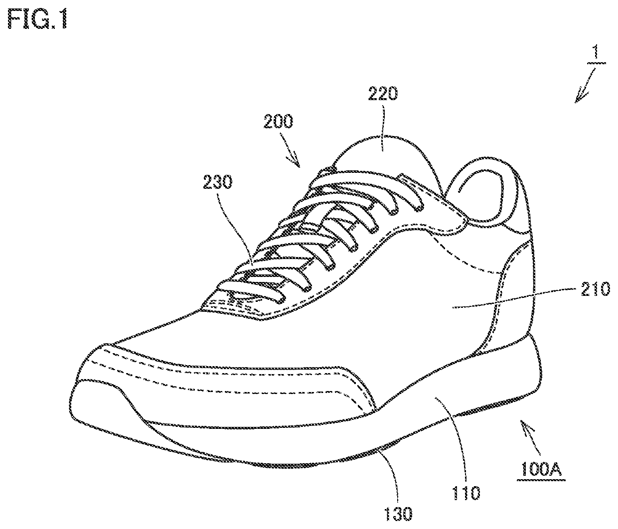
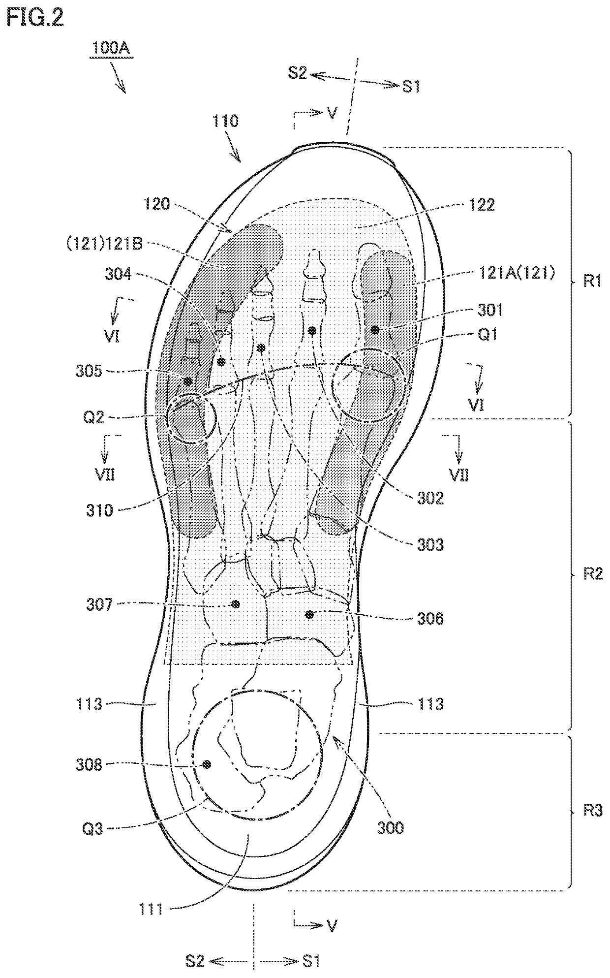
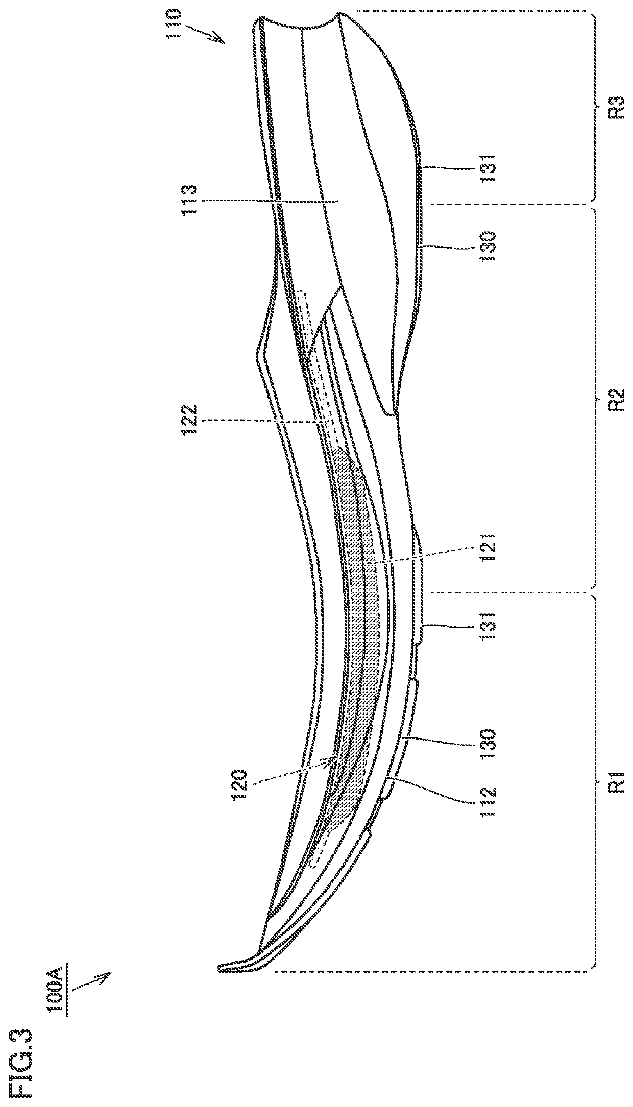
[0055]FIG. 1 is a schematic perspective view of a shoe sole and a shoe including the shoe sole, according to a first embodiment. Referring to FIG. 1, schematic configurations of a shoe 1 and a shoe sole 100A according to the present embodiment will be described below.
[0056]As shown in FIG. 1, the shoe 1 includes a shoe sole 100A and an upper 200. The shoe sole 100A is a member covering a sole of a foot and having a substantially flat shape. The upper 200 has a bag-like shape enclosing the entire foot inserted into a shoe and is positioned above the shoe sole 100A.
[0057]The upper 200 includes an upper body 210, a shoe tongue 220, and a shoelace 230. The upper body 210 has a bag-like shape as described above. Both the shoe tongue 220 and the shoelace 230 are fixed or attached to the upper body 210.
[0058]The upper body 210 has: a lower portion having a bottom portion to be fixed to the shoe sole 100A; and an upper portion provided with an opening through which an upper part of an ankle...
first modification
[0106]FIG. 9 is a schematic longitudinal cross-sectional view of a shoe sole according to a first modification based on the above-described first embodiment. FIG. 10 is a schematic transverse cross-sectional view taken along a line X-X shown in FIG. 9. The following describes a shoe sole 100A1 according to the present modification with reference to FIGS. 9 and 10. The shoe sole 100A1 according to the present modification is provided in the shoe 1 in place of the shoe sole 100A according to the above-described first embodiment.
[0107]As shown in FIGS. 9 and 10, when comparing the shoe sole 100A1 according to the present modification with the shoe sole 100A according to the above-described first embodiment, the position of the highly rigid member 120 is the main difference therebetween. Specifically, in the shoe sole 100A1, the highly rigid member 120 is not embedded in the midsole 110 but is disposed on the upper surface 111 of the midsole 110 and fixed to the midsole 110. The highly ...
second modification
[0110]FIG. 11 is a schematic longitudinal cross-sectional view of a shoe sole according to a second modification based on the above-described first embodiment. FIG. 12 is a schematic transverse cross-sectional view taken along a line XII-XII shown in FIG. 11. The following describes a shoe sole 100A2 according to the present modification with reference to FIGS. 11 and 12. Note that the shoe sole 100A2 according to the present modification is provided in the shoe 1 in place of the shoe sole 100A according to the above-described first embodiment.
[0111]As shown in FIGS. 11 and 12, when comparing the shoe sole 100A2 according to the present modification with the shoe sole 100A according to the above-described first embodiment, the position of the highly rigid member 120 is the main difference therebetween. Specifically, in the shoe sole 100A2, the highly rigid member 120 is not embedded in the midsole 110 but is disposed on the lower surface 112 of the midsole 110 and fixed to the midso...
PUM
 Abstract
Description
Claims
Application Information
 - R&D
- Intellectual Property
- Life Sciences
- Materials
- Tech Scout
- Unparalleled Data Quality
- Higher Quality Content
- 60% Fewer Hallucinations
Browse by: Latest US Patents, China's latest patents, Technical Efficacy Thesaurus, Application Domain, Technology Topic, Popular Technical Reports.
© 2025 PatSnap. All rights reserved.Legal|Privacy policy|Modern Slavery Act Transparency Statement|Sitemap|About US| Contact US: help@patsnap.com


