
Heat dissipation apparatus for a linear motor

a technology of heat dissipation apparatus and linear motor, which is applied in the direction of magnetic circuit rotating parts, magnetic circuit shape/form/construction, windings, etc., can solve the problems of wasting a lot of effective power, slow heat dissipation of the abovementioned heat dissipation methods, etc., and achieves the effect of increasing the continuous current and the propelling force of the linear motor

Inactive Publication Date: 2007-08-02
HIWIN MIKROSYST
View PDF3 Cites 5 Cited by
  • Summary
  • Abstract
  • Description
  • Claims
  • Application Information

AI Technical Summary

Benefits of technology

[0007] The primary objective of the present invention is to solve the aforesaid problems by providing a heat dissipation apparatus for a linear motor that can increase the continuous current and the propelling force of the linear motor.
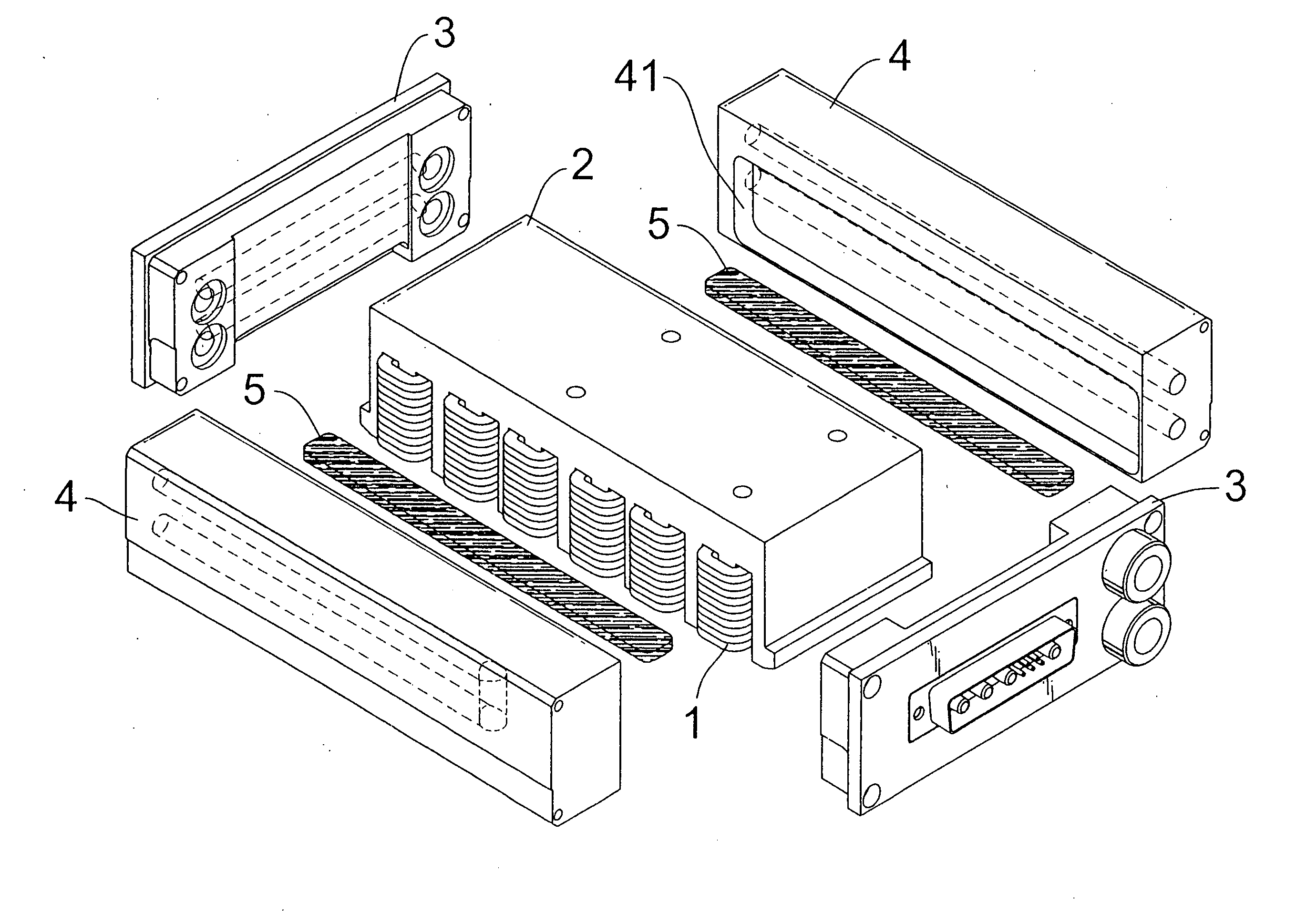
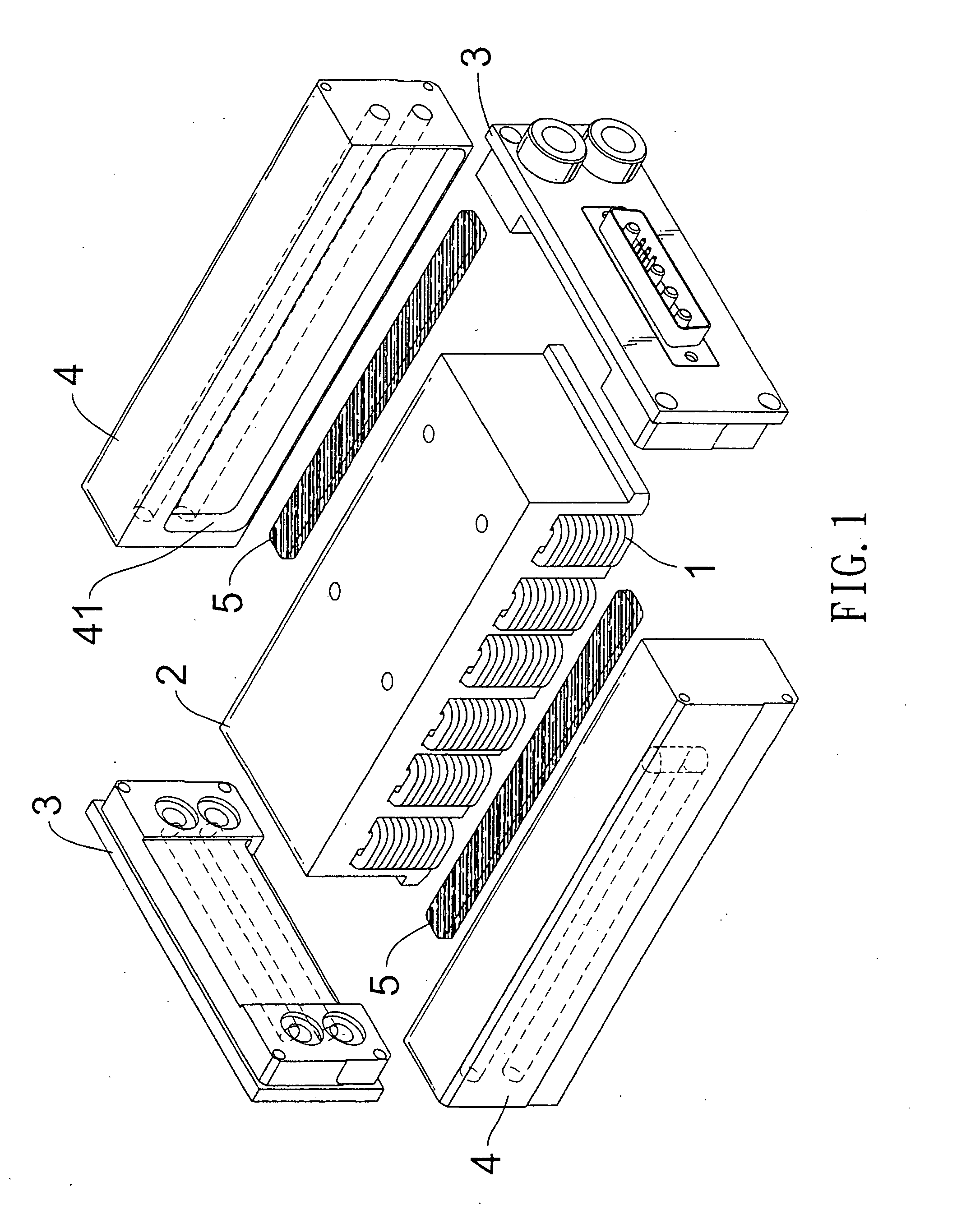
[0008] To achieve the abovementioned objective, the present invention provides a heat dissipation apparatus for a linear motor comprising a motor iron core wound with windings, and a pair of covers and a pair of dissipation mechanisms being arranged at two pairs of opposite sides of the motor iron core, respectively, which is characterized in that: a groove is defined in an inner side of the respective dissipation mechanisms at two opposite sides of the motor iron core for accommodation of heat dissipation medium, such that the coefficient of thermal conductivity of the windings on the motor iron core and the heat dissipation mechanisms are increased, improving the heat dissipation effect.

Problems solved by technology

According to our many years experience in the related field, we found that the heat dissipation of the abovementioned heat dissipation methods is relatively slow and can't effectively take the heat source away, wasting a lot of effective power.

Method used


Image

  • Heat dissipation apparatus for a linear motor
  • Heat dissipation apparatus for a linear motor
  • Heat dissipation apparatus for a linear motor

Examples


Embodiment Construction

[0014] The foregoing, and additional objects, features and advantages of the present invention will become apparent from the following detailed description of preferred embodiments thereof, taken in conjunction with the accompanying drawings.

[0015] Referring to FIGS. 1-4, the embodiments are shown by way of example and not limitation.

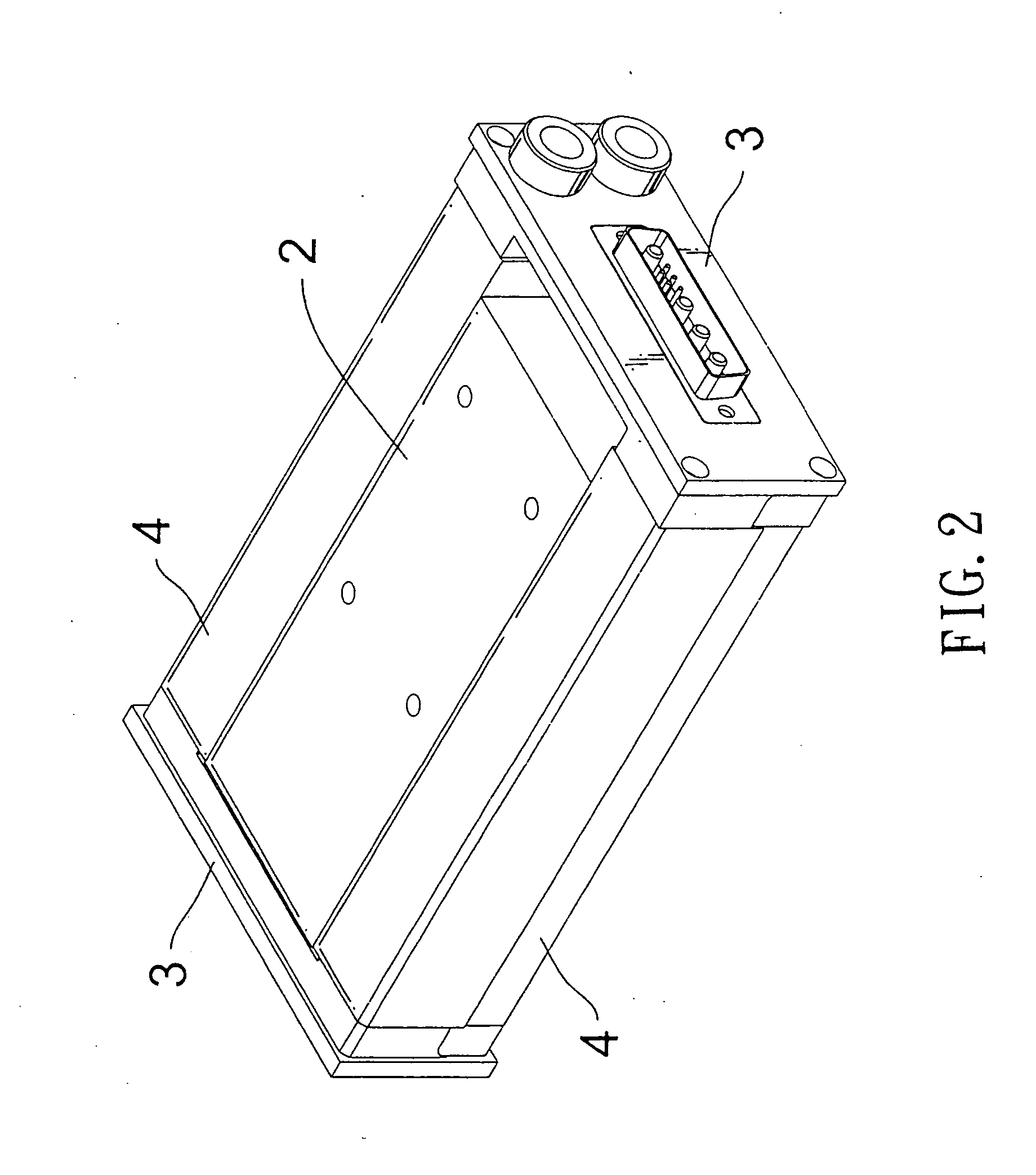
[0016] Referring to FIGS. 1 and 3 firstly, a heat dissipation apparatus for a linear motor in accordance with the present invention comprises a motor iron core 2 wound with windings 1, and a pair of covers 3 and a pair of dissipation mechanisms 4 are arranged at two pairs of opposite sides of the motor iron core 2, respectively. The present invention is characterized in that: a groove 41 is defined in the inner side of each of the dissipation mechanisms 4 for accommodation of heat dissipation medium 5 (which is thermal conductive grease for example), such that the coefficient of thermal conductivity of the windings 1 on the motor iron core 2 and that ...


PUM


Abstract

A heat dissipation apparatus for a linear motor comprises a motor iron core wound with windings, and a pair of covers and a pair of dissipation mechanisms being arranged at two pairs of opposite sides of the motor iron core, respectively, which is characterized in that: a groove is defined in an inner side of the respective dissipation mechanisms at two opposite sides of the motor iron core for accommodation of heat dissipation medium, such that the coefficient of thermal conductivity of the windings on the motor iron core and the heat dissipation mechanisms are increased, improving the heat dissipation effect.

Description

BACKGROUND OF THE INVENTION [0001] 1. Field of the Invention [0002] The present invention relates to a linear motor mechanism, and more particularly to a heat dissipation apparatus for a linear motor that can improve the heat dissipation effect, and can increase the continuous current and the propelling force of the linear motor. [0003] 2. Description of the Prior Art [0004] The existing heat dissipation methods used in a linear motor generally include air cooling, water cooling, external heat sink or external fans, etc. According to our many years experience in the related field, we found that the heat dissipation of the abovementioned heat dissipation methods is relatively slow and can't effectively take the heat source away, wasting a lot of effective power. As a result of that, it is unable to let the linear motor increase its continuous current and to improve the propelling force of the linear motor. [0005] Hence, the conventional design of the heat dissipation structure of the...

Claims


Application Information

Patent Timeline
Patent Type & Authority Applications(United States)
IPC IPC(8): H02K41/00H02K3/24
CPCH02K5/20H02K41/02H02K9/22H02K9/223
Inventor HUANG, LIEH-FENGHUNG, CHIA-CHUN
Owner HIWIN MIKROSYST
Learn More