
Personal watercraft

a technology for watercraft and nozzles, applied in the field of personal watercraft, can solve the problems of increasing the number of components, increasing the number of assembly steps, and lowering the propulsion force, so as to reduce the resistance of the flow passage of the steering nozzle, improve the propulsion force, and efficiently eject the

Inactive Publication Date: 2005-07-05
HONDA MOTOR CO LTD
View PDF5 Cites 8 Cited by
  • Summary
  • Abstract
  • Description
  • Claims
  • Application Information

AI Technical Summary

Benefits of technology

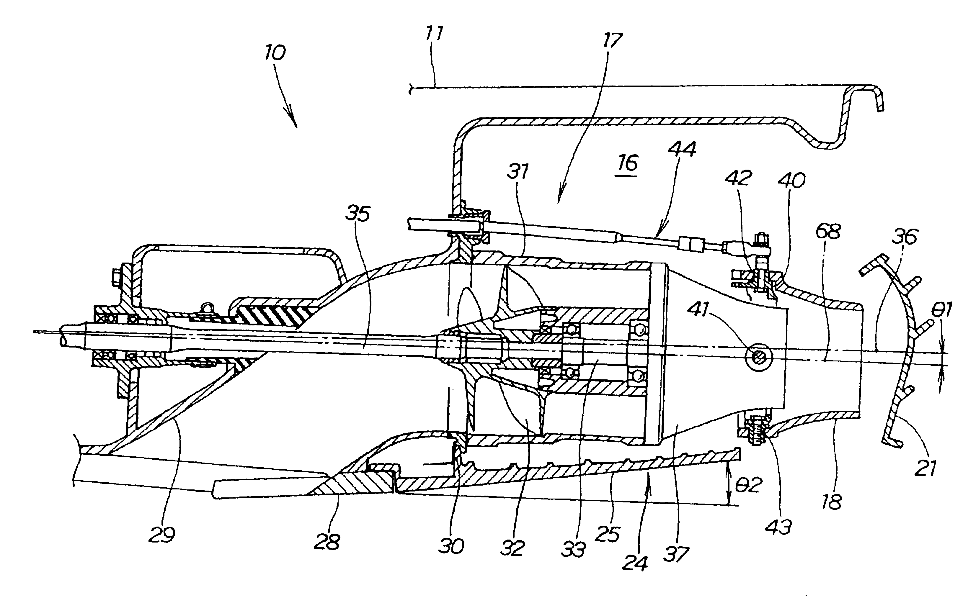
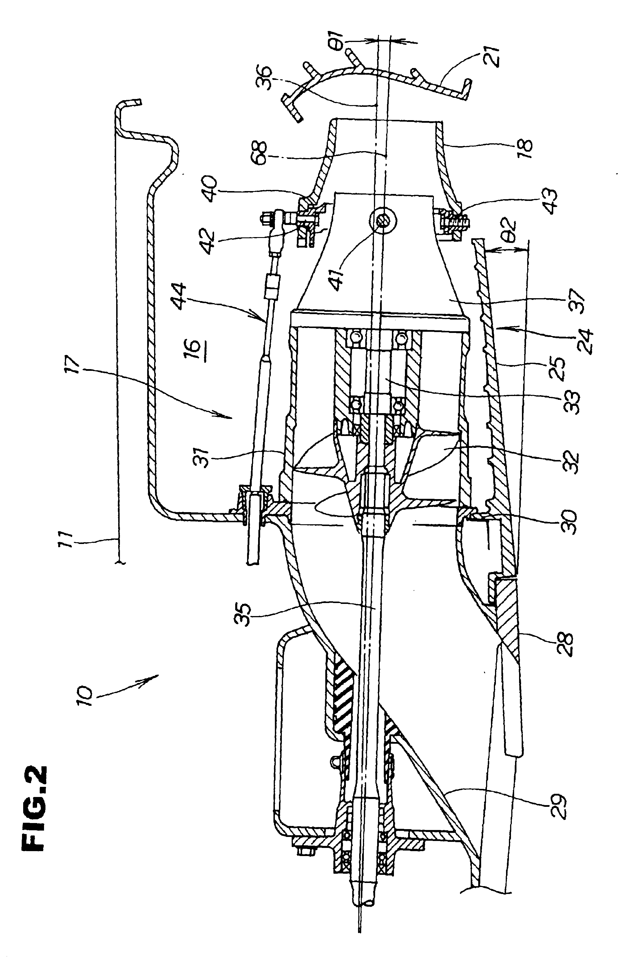
[0016]The axis of the jet propeller is set with the rearwardly downward gradient, and the jet direction of the jet water ejected from the steering nozzle is made to coincide with the axis of the jet propeller. Therefore, the flow passage resistance of the steering nozzle can be reduced, the jet water can be efficiently ejected, and the propulsion force can be enhanced.
[0017]In addition, with the bottom surface of the stern set with the rearwardly upward gradient, the volume of the bottom surface can be reduced as compared with an ordinary stern bottom surface, and the buoyancy can be reduced by an amount corresponding to the volume reduced. Therefore, the buoyancy on the stern can be reduced as compared with the buoyancy on the ordinary stern, resulting in that it is easier for the stern to sink underwater.
[0018]Therefore, when the jet force of the jet water is increased to put the personal watercraft into a planing condition, a force for lifting up the stern is generated because the jet direction of the jet water is downward, but, since the bottom surface of the stern is set with the rearwardly upward gradient, front and rear portions of the hull can be favorably floated up from the surface of water, and the personal watercraft can plane in a favorable posture.
[0020]With the steering nozzle thus vertically movable, the jet direction of the jet water can be appropriately adjusted in the vertical direction during planing of the personal watercraft, so that the hull can be maintained in a favorable planing posture. On the other hand, the jet direction of the jet water ejected from the steering nozzle is made to coincide with the axis of the jet propeller at the standard position during navigation. With the standard position made to be a position during navigation or planing of the personal watercraft, and with the steering nozzle set free at the time of navigation or planing, the steering nozzle is returned into the standard position by the force of the jet water ejected by the jet propeller, so that there is no need for a member for maintaining the steering nozzle in the standard position. By this, the structure for vertically swinging the steering nozzle can be simplified.

Problems solved by technology

However, where the steering nozzle is disposed with the rearwardly upward gradient, the jet water from the jet propeller is deflected by the steering nozzle, so that the flow passage resistance is increased, resulting in a lowering of the propulsion force.
In addition, where the steering nozzle is disposed with the rearwardly upward gradient, the constitution is complicated, and the number of component parts and the number of assembling steps are increased.

Method used


Image

  • Personal watercraft
  • Personal watercraft
  • Personal watercraft

Examples


Embodiment Construction

[0037]An embodiment of the present invention will be described below. Here, the terms “front”, “rear”, “left” and “right” have the respective meanings as viewed from the driver. The drawings are to be looked at according to the posture of symbols.

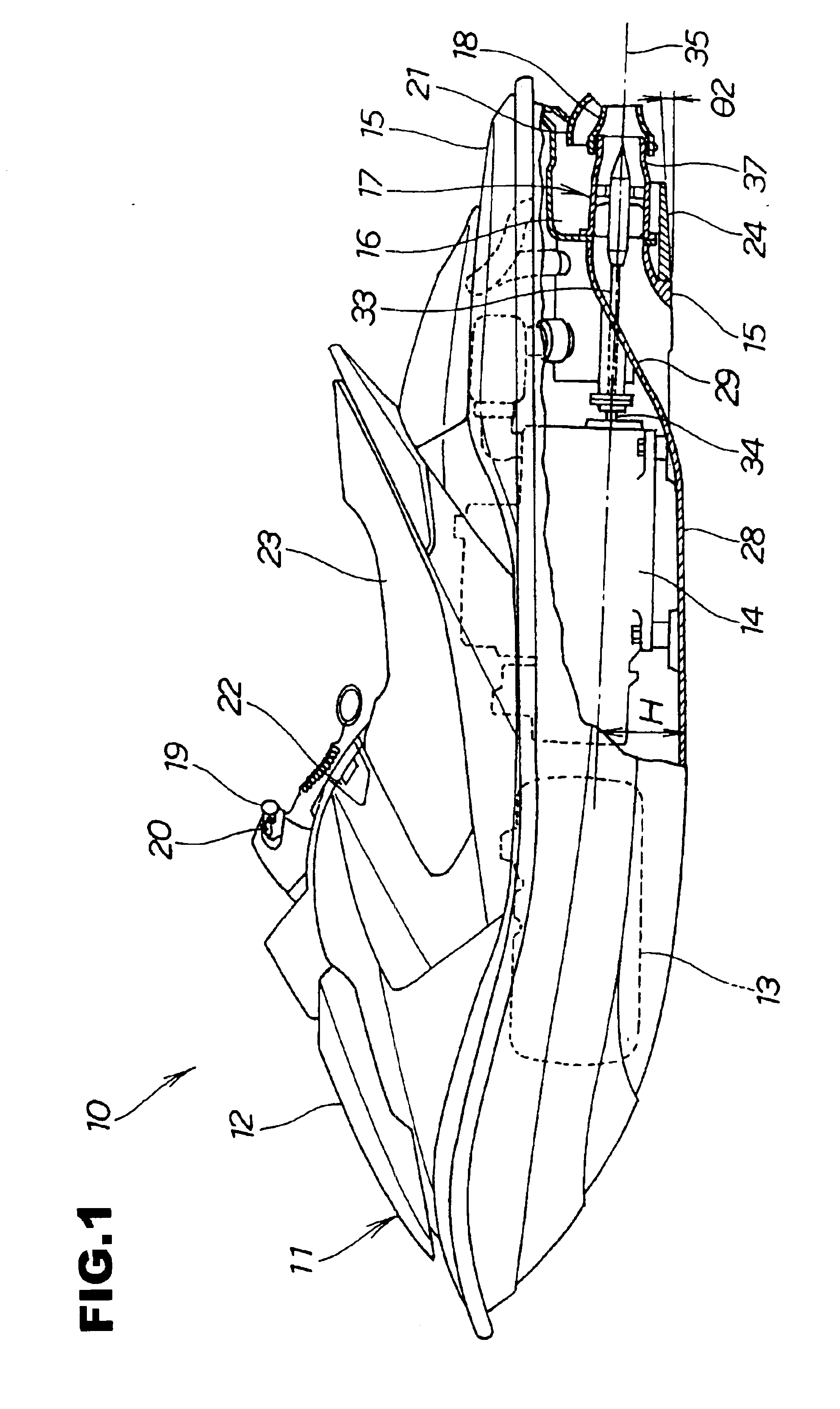
[0038]FIG. 1 is a side view of a personal watercraft according to the present invention. The personal watercraft 10 has a structure in which a fuel tank 13 is provided at a front portion 12 of a hull 11, an engine 14 is provided on the rear side of the fuel tank 13, a jet propeller chamber 16 is provided at a stern 15 on the rear side of the engine 14, a water jet propeller (jet propeller) 17 is provided in the jet propeller chamber 16, a steering nozzle 18 is provided on the rear side of the water jet propeller 17, a steering handle 19 for swinging the steering nozzle 18 in the left-right direction is provided on the upper side of the fuel tank 13, a trim operating lever 20 for swinging the steering nozzle 18 vertically is provided on the ...


PUM


Abstract

A personal watercraft having an engine, a water jet propeller on the rear side of the engine, a jet nozzle for ejecting jet water, and a steering nozzle swingable in the left-right direction. The axis of the water jet propeller is set with a rearwardly downward gradient at an angle θ1, and the bottom surface of a ride plate is set with a rearwardly upward gradient at an angle θ2.

Description

BACKGROUND OF THE INVENTION[0001]1. Field of the Invention[0002]The present invention relates to a personal watercraft which navigates by the jet force of jet water through ejecting the jet water rearwards from a jet nozzle provided at a rear portion of a hull.[0003]2. Description of the Related Art[0004]Personal watercraft for navigating or planing on the waters of the sea and lakes are generally known. An example of such a personal watercraft is described in Japanese Patent Laid-open No. Hei 9-281132 and will be described below.[0005]The personal watercraft includes an engine and a jet propeller driven by the engine which are disposed in a hull, and a steering nozzle provided at the rear end of the jet propeller. The jet propeller is driven by the engine, whereby an impeller of a water jet propeller is rotated, and water is sucked in through an intake port by the rotation of the impeller.[0006]The water thus sucked in is ejected as jet water rearwards from the rear end of the stee...

Claims


Application Information

Patent Timeline
Patent Type & Authority Patents(United States)
IPC IPC(8): B63H11/00B63B1/16B63B1/18B63H11/113B63B35/73B63B1/08B63B1/00B63H11/103B63H11/08
CPCB63B1/18B63H11/113B63B1/08B63B35/731Y02T70/128B63B34/10Y02T70/10
Inventor FUSE, TOMOHIROTSUCHIYA, MASAHIKOKOCHI, TAKAO
Owner HONDA MOTOR CO LTD
Learn More