
Linear actuator

A linear actuator and coil technology, applied in electrical components, electromechanical devices, etc., can solve the problems of heat generation, discharge, and restriction of coils, and achieve the effects of simple structure, reduced cost and size, and fast response time.

Inactive Publication Date: 2013-07-03
AKRIBIS SYST SHANGHAI
View PDF3 Cites 5 Cited by
  • Summary
  • Abstract
  • Description
  • Claims
  • Application Information

AI Technical Summary

Problems solved by technology

Another disadvantage of voice coil actuators is that the coil generates heat
Since the coil group is a moving part, the heat cannot be dissipated by other means except through the load
This is not advisable as it will cause thermal expansion of the load which will affect motion accuracy
Also, the continuous current flow of the actuator is limited by the fact that the heat cannot escape elsewhere

Method used


Image

  • Linear actuator
  • Linear actuator
  • Linear actuator

Examples


Embodiment Construction

[0032] In order to have a further understanding and understanding of the structural features of the present invention and the achieved effects, the preferred embodiments and accompanying drawings are used for a detailed description, as follows:

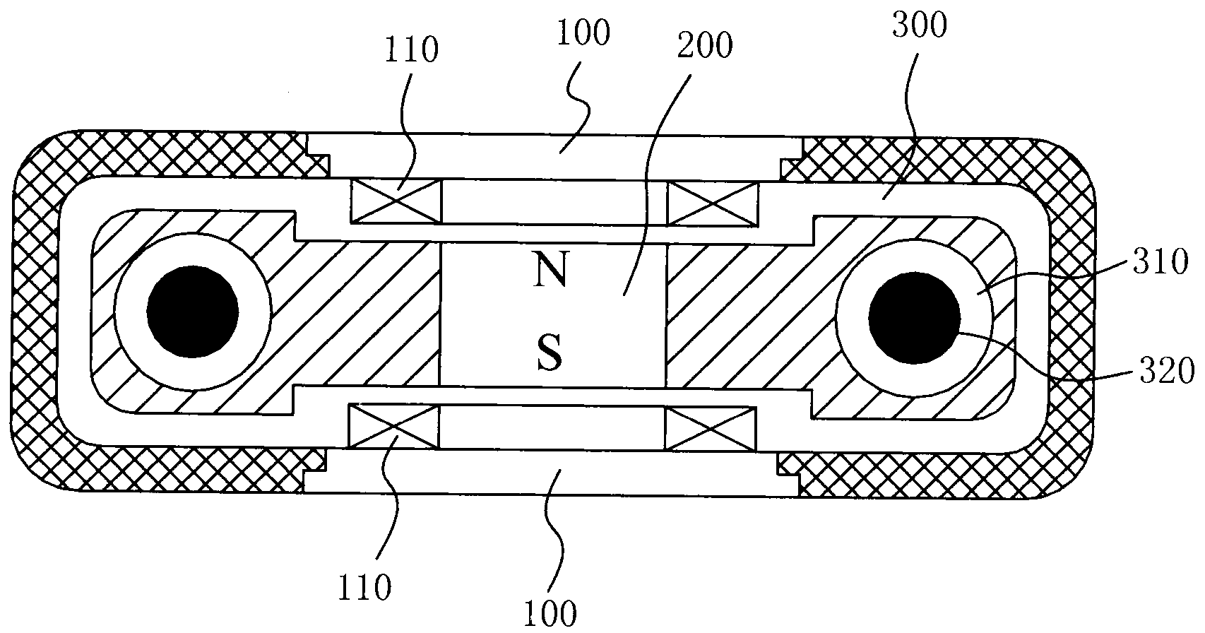
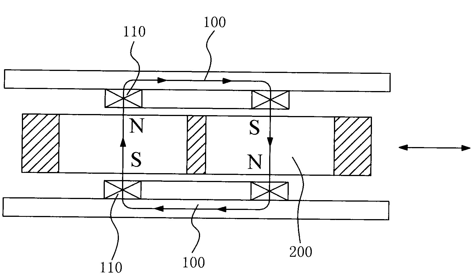
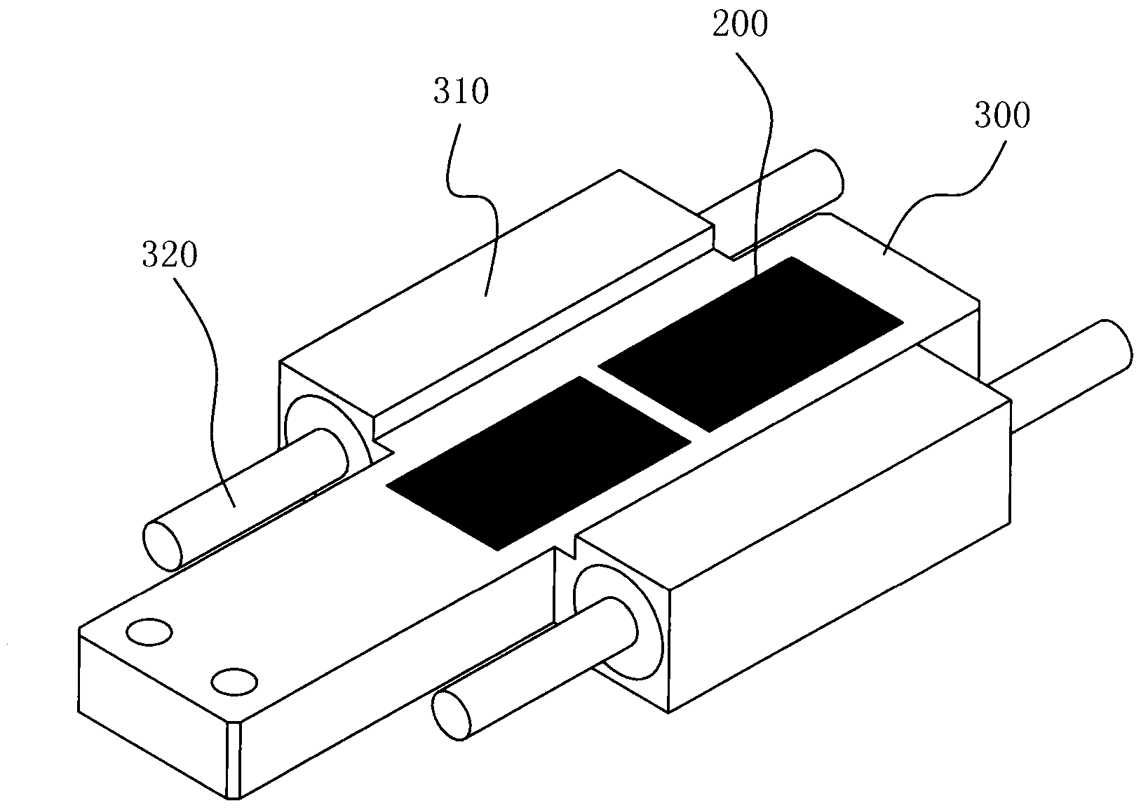
[0033] see figure 1 , a linear actuator, including a coil back iron 100 and a magnet 200, the coil back iron 100 is arranged at one end of the magnet 200, a coil 110 is wound on the coil back iron 100, in the present invention, the coil back iron 100 includes two , two coil back irons 110 are arranged on the upper end and the lower end of the magnet 200 respectively, the distance between the two coil back irons 100 and the magnet 200 is the same, and a magnet support structure 300 is also included, and the magnet support structure 300 includes The two bushes 310 are connected to the two fixed shafts 320 , and the two bushes 310 slide along the two fixed shafts 320 .

[0034] In the present invention, the coil 110 wound on the coil ba...


PUM


Abstract

The invention relates to a linear actuator which comprises coil back iron and magnetic iron. The coil back iron is arranged at one end of the magnetic iron, a coil is wound on the coil back iron, the number of the coil back iron is two, the two coil iron bodies are arranged at the upper end and the lower end of the magnetic iron, distances from each of the two coil iron bodies to the magnetic iron are identical, and the linear actuator further comprises a magnetic iron supporting structure. The magnetic iron supporting structure comprises two bushes connected on the two sides of the magnetic iron, and the two bushes are connected on two fixed shafts and slide along the two fixed shafts. The linear actuator has the advantages of being stable in structure, good in transmission effect, prone to heat dissipation and easy to control.

Description

technical field [0001] The invention relates to a linear actuator, in particular to a linear actuator which adopts the design of a moving magnetic double-sided coil and does not use any magnet back iron. Background technique [0002] Pneumatic actuators have been widely used in industrial automation over the past few decades. This is due to the low cost of compressed air, the simple and reliable function of the pneumatic actuators, and the high availability of auxiliary components and products. However, if a pneumatic actuator is to be used, a flexible compressed air hose must be connected to the actuator. For portable equipment and off-site equipment, obtaining compressed air can be difficult. As a result, pneumatic actuators can only be used in facilities with compressed air. In addition, valve devices such as solenoid valves are often used to control the air flow in the actuator. Other sensors are also required to detect the position of the actuator stem. All necessa...

Claims


Application Information

Patent Timeline
Patent Type & Authority Applications(China)
IPC IPC(8): H02K33/18
Inventor 林浩元周朝渊曾振武
Owner AKRIBIS SYST SHANGHAI
Learn More