
An automatic auxiliary bench for machining with automatic control of the clamping force

A machining and automatic technology, applied in the direction of metal processing equipment, metal processing machinery parts, manufacturing tools, etc., can solve the problems of inconvenient automatic adjustment, insufficient structure of automatic control of top tightening force, inconvenient adjustment of fixed radian, etc.

Active Publication Date: 2021-07-30
江苏富乐德石英科技有限公司
View PDF6 Cites 0 Cited by
  • Summary
  • Abstract
  • Description
  • Claims
  • Application Information

AI Technical Summary

Problems solved by technology

[0005] In order to solve the above-mentioned technical problems, the present invention provides an automatic auxiliary bench for machining with automatic control of the jacking force, so as to solve the problem that most of the structure of the automatic control of the jacking force is not perfect, or there is no function of this mechanism at all. , it is not convenient to automatically adjust after being clamped to a certain strength according to the demand, and when the existing automatic auxiliary bench is in use, the arc of adjusting the fixed position is not perfect enough, and it is not convenient to adjust the fixed arc according to the demand, so that it is convenient for users with The problem of fixing parts with arc structure

Method used


Image

  • An automatic auxiliary bench for machining with automatic control of the clamping force
  • An automatic auxiliary bench for machining with automatic control of the clamping force
  • An automatic auxiliary bench for machining with automatic control of the clamping force

Examples


Embodiment

[0032] as attached figure 1 To attach Figure 8 Shown:

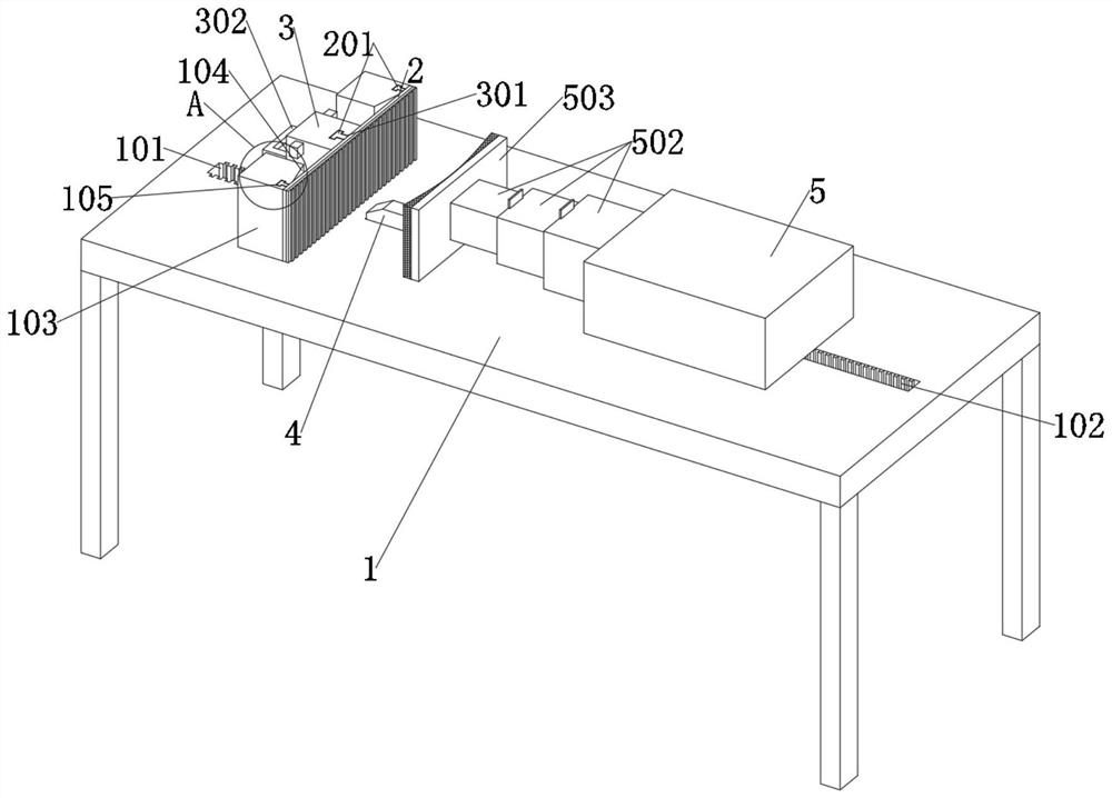
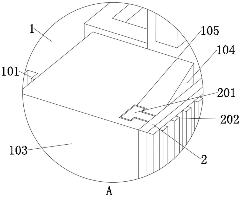
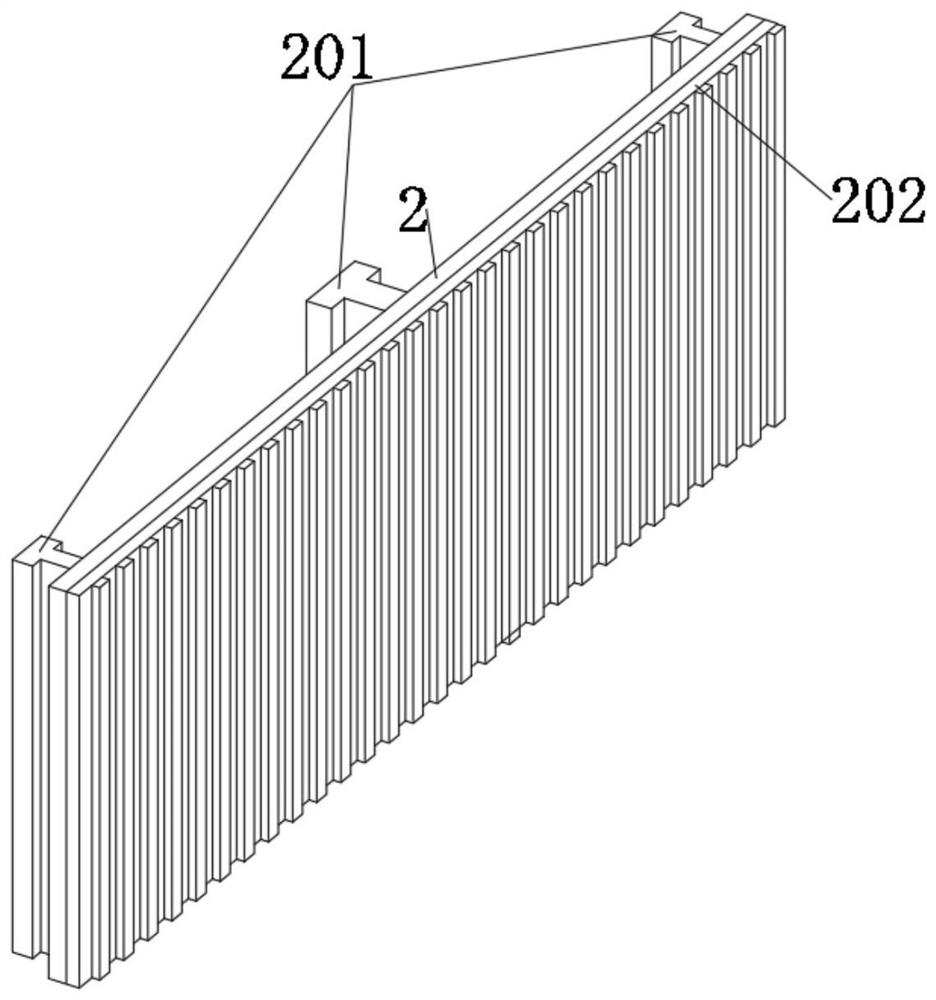
[0033]The present invention provides an automatic auxiliary bench for machining with automatic control of the jacking force. Chuck 201, anti-slip piece 202, moving piece 3, embedded groove 301, pulling piece 302, inner compartment 303, pressing piece 304, clamping piece 305, receiving piece 4, triggering piece 401, moving box 5, motor 501, telescopic piece 502 , a splint 503, a force member 6, a contact block 601, a trigger block 602 and a pressure plate 603; the main body 1 is a rectangular plate structure, and the bottom corner of the main body 1 is installed with a support rod of a rectangular structure by welding, and the main body 1 is provided with a moving slot 102 with a rectangular structure in the middle position on the right side of the top, and the gear at the bottom of the motor 501 is installed inside the moving slot 102; the right side of the mounting block 103 is provided with a T-shaped mounting slot 1...


PUM


Abstract

The invention provides an automatic auxiliary bench for machining with automatic control of the jacking force, including: clamping parts, receiving parts, triggering parts, moving bins, motors, telescopic parts, splints, force-bearing parts, contact blocks, and trigger blocks and the pressure plate; the inner right side of the moving compartment is equipped with a motor through a connecting piece, and the bottom of the motor is equipped with a gear through a transmission shaft, and the left side of the splint is installed with a rubber material with an arc-shaped structure on the left side by bonding. Anti-slip mat, and the bottom of the telescopic part is equipped with a pulley through the connecting part and the rotating shaft; the spring plate here is used to be pulled by the moving part, so that the spring plate can be in different bending arcs, so that it is convenient to carry out parts with arcs. Fixing, so that the parts with arc structure can be firmly fixed, and the chuck is used to drive the spring plate for installation, so that the spring plate can be connected with the moving part and the installation block through the chuck.

Description

technical field [0001] The invention belongs to the technical field of auxiliary benches, and more specifically relates to an automatic auxiliary bench for machining with automatic control of the tightening force. Background technique [0002] The auxiliary bench is used to fix items or parts, so as to facilitate the testing or processing of the parts, so that the parts can be tested or processed. [0003] Such as the invention patent, application number: 201510843795.7, a workpiece assembly workbench, abstract: the present invention provides a workpiece assembly workbench, including a frame and at least one platform module, each of which includes an adjustment unit and two Two platforms are arranged at intervals on the surface of the frame, two workpieces are respectively placed on the two platforms, and the adjustment unit adjusts and positions the horizontal distance between the two workpieces. The invention provides a workbench for workpiece assembly that requires high ...

Claims


Application Information

Patent Timeline
Patent Type & Authority Patents(China)
IPC IPC(8): B23Q1/72B23Q1/74B23Q3/06
CPCB23Q1/72B23Q1/74B23Q3/06
Inventor 刘世杰
Owner 江苏富乐德石英科技有限公司
Learn More