Method for displaying user interface and electronic device therefor

a user interface and electronic device technology, applied in the field of displaying a user interface and an electronic device, can solve the problems of accident that may occur, user may not perceive surrounding situations, and difficulty for the user to perceive the presence of surrounding objects or people, and achieve the effects of minimizing the display of a user interface, avoiding accidental collision with external objects, and avoiding accidental collision

Pending Publication Date: 2022-05-19
SAMSUNG ELECTRONICS CO LTD
View PDF40 Cites 1 Cited by
  • Summary
  • Abstract
  • Description
  • Claims
  • Application Information

AI Technical Summary

Benefits of technology

[0009]According to various example embodiments of the disclosure, an electronic device may provide intuitive and convenient usability by flexibly changing a user interface displaying method based on a user's states.
[0010]The user may employ wearable glasses more safely by simplifying and / or minimizing the display of a user interface or by terminating the display of the user interface when it is determined that the user's motion information obtained using a sensor exceeds a specified reference.

Problems solved by technology

However, because user interfaces are displayed while being overlaid on a user's visual field, the user may not perceive surrounding situations.
For example, when the user wears wearable glasses while he / she is walking or running, it may be difficult for the user to perceive the presence of surrounding objects or people.
In the worst case, an accident that collides with external objects may occur.

Method used


Image

  • Method for displaying user interface and electronic device therefor
  • Method for displaying user interface and electronic device therefor
  • Method for displaying user interface and electronic device therefor

Examples


Embodiment Construction

[0027]Hereinafter, various example embodiments of the disclosure will be described in greater detail with reference to the accompanying drawings. However, it should be understood that the disclosure is not limited to specific embodiments, but rather includes various modifications, equivalents and / or alternatives of the embodiments of the present disclosure. Regarding description of the drawings, like reference numerals may refer to like elements.

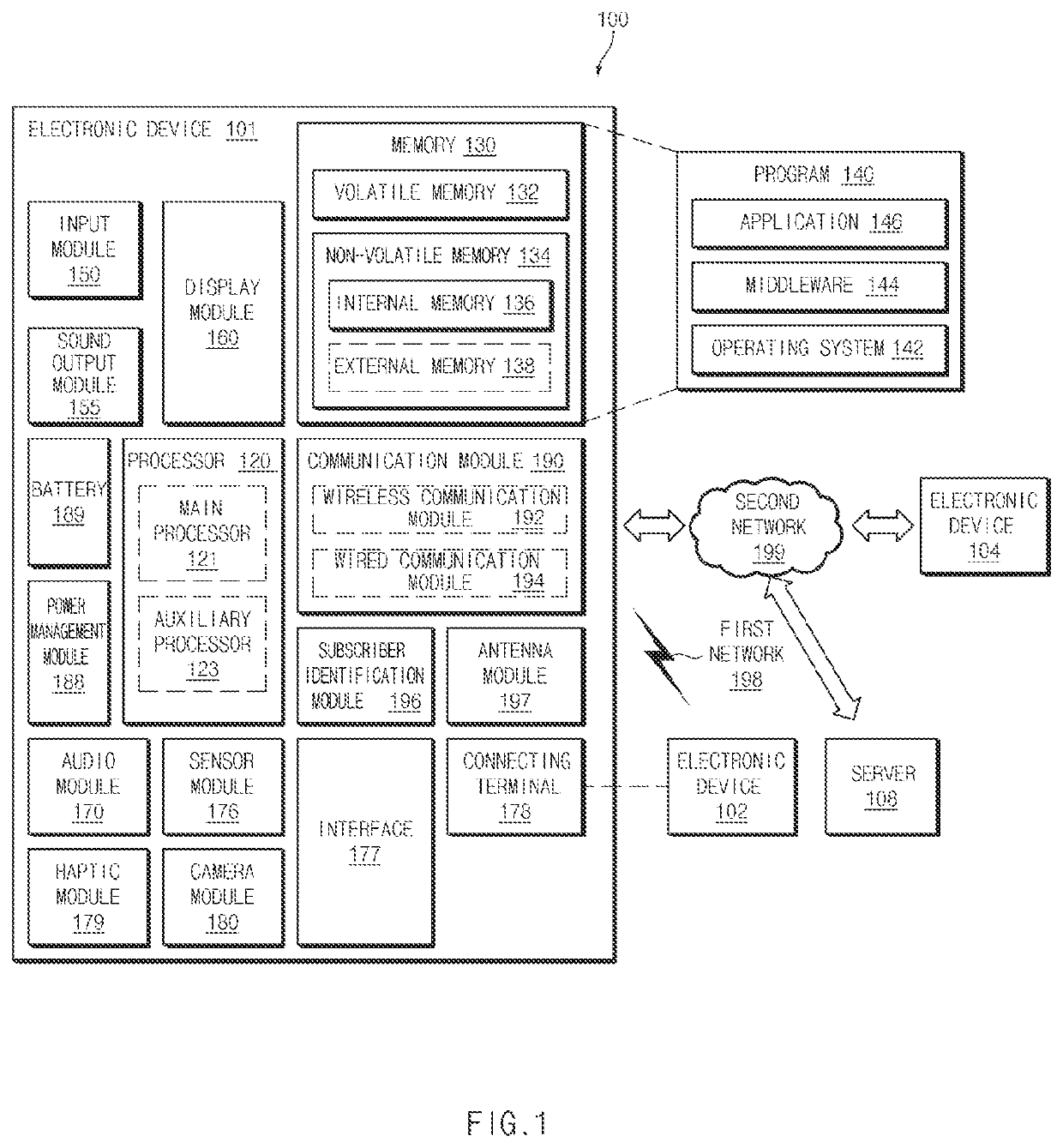
[0028]FIG. 1 is a block diagram illustrating an example electronic device 101 in a network environment 100 according to various embodiments. Referring to FIG. 1, the electronic device 101 in the network environment 100 may communicate with an electronic device 102 via a first network 198 (e.g., a short-range wireless communication network), or at least one of an electronic device 104 or a server 108 via a second network 199 (e.g., a long-range wireless communication network). According to an embodiment, the electronic device 101 may communic...


PUM


Abstract

Disclosed is an electronic device including: a camera, a transparent display including a first area corresponding to a first visual field area and a second area corresponding to a second visual field area, at least one sensor, a processor, and a memory operatively connected to the processor. The electronic device may obtain motion information of the electronic device including a movement speed using the at least one sensor, may display a first user interface including at least one graphic user interface (GUI) corresponding to an application execution screen in the first area of the transparent display based on the movement speed not being greater than a first speed, and may display the at least one GUI in the second area based on the movement speed exceeding the first speed.

Description

CROSS-REFERENCE TO RELATED APPLICATIONS[0001]This application is a national stage of International Application No. PCT / KR2021 / 013564 designating the United States, filed on Oct. 5, 2021, in the Korean Intellectual Property Receiving Office and claiming priority to Korean Patent Application No. 10-2020-0152766, filed on Nov. 16, 2020, in the Korean Intellectual Property Office, the disclosures of which are incorporated by reference herein in their entireties.BACKGROUNDField[0002]The disclosure relates to a method for displaying a user interface and an electronic device supporting the same.Description of Related Art[0003]As a technology associated with a wearable electronic device develops, various types of wearable electronic devices are being released. The wearable electronic device may be referred to as an “electronic device” that a person is capable of wearing and using. For example, various types of wearable electronic devices such as a wearable watch, wearable glasses, and / or a ...

Claims


Application Information

Patent Timeline
Patent Type & Authority Applications(United States)
IPC IPC(8): G06F3/0481G02B27/01G06F3/0484
CPCG06F3/0481G02B27/017G02B27/0179G06F2203/04804G02B2027/0141G02B2027/014G02B2027/0187G06F3/0484G02B27/0172G02B27/0093G02B2027/0138G06F1/163G06F2203/04803G06F3/011G06F1/1694G06F3/012G06F3/013
Inventor JEONG, EUNSU
Owner SAMSUNG ELECTRONICS CO LTD
Why Eureka
Try Eureka