
Eureka
For R&D, Eureka makes reading and utilizing patents & technical documents easy.
Eureka AIR
Designed for self-driven R&D workflows. Generate viable solutions, solve complex R&D challenges, empower your innovation with AI.

Eureka Materials
Designed for material experts only. Revolutionize your material R&D, from search, analyze, to developing new materials.

TechResearch
Generate reliable direction feasibility study reports for your R&D in just a few steps.

TechSeek
Discover and master advanced knowledge NOW. Basics, ideas, possibilities, all at once.

TechMind
As an expert in R&D Theories, TechMind can generates customized viable solutions instantly.

TechRisk
Analyze your overall solution with one click, know your potential R&D risks in advance.

TechMonitor
Get weekly tech updates, stay abreast of the latest tech innovations and key insights.
Detecting device and measuring device
- Summary
- Abstract
- Description
- Claims
- Application Information
AI Technical Summary
Benefits of technology
Problems solved by technology
Method used
Image

Examples
first embodiment
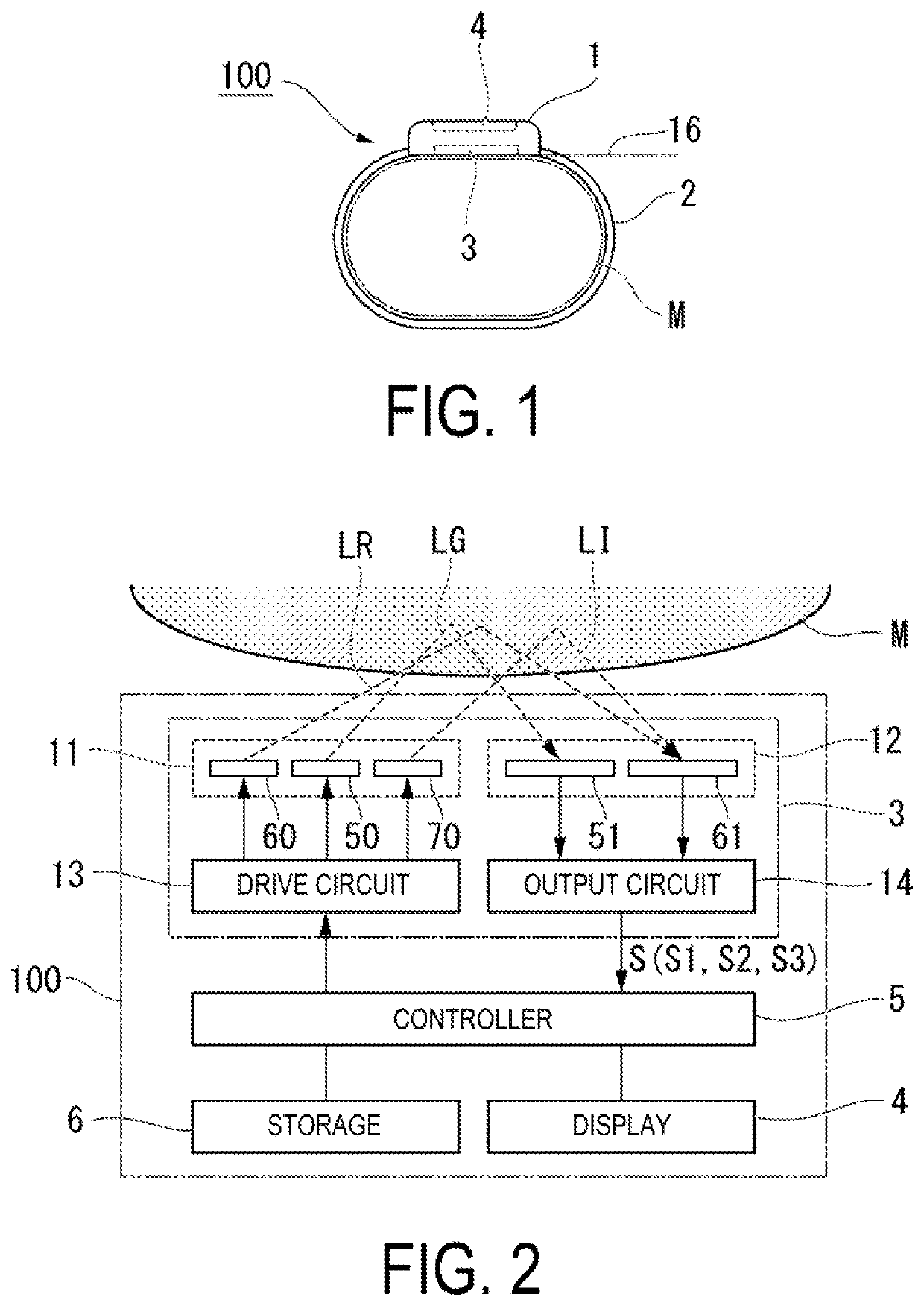
[0029]FIG. 1 is a side view of a measuring device 100 of the first embodiment. The measuring device 100 of the first embodiment illustrated in FIG. 1 is a biometric measuring that non-invasively measures biometric information of an examinee (for example, a human) that an exemplification of a biological body, and is mounted on a site to be measured (hereinafter referred to as “measurement site”) M in the biological body of the examinee. The measuring device 100 of the first embodiment is a wrist-watch type portable appliance equipped with a housing portion 1 and a belt 2, and is attachable to a wrist of the examinee by winding the band shaped belt 2 around the wrist that is an exemplification of the measurement site (biological M. In the first embodiment, a pulse wave (for example, a pulse rate) and an oxygen saturation (SpO2) are exemplified as the biometric information. The pulse wave means a time variation in volume inside a vessel that operates in conjunction with the beats of a ...
second embodiment
[0095]Next, a detecting device of the second embodiment will be described. In the first embodiment, an example is given of a case where the light-receiving unit 61 receives both the red light LR and the near-infrared light LI, and a detecting device 3A of the second embodiment differs from the detecting device 3 of the first embodiment in that a light-receiving unit is provided that individually receives the red light LR and the near-infrared light LI.
[0096]FIG. 7 is a plan view of a detecting device of the second embodiment. FIG. 8 is a cross-sectional view taken along the line VIII-VIII in FIG. 7.
[0097]A light-receiving unit portion 112 of the detecting device 3A of the second embodiment includes a light-receiving unit (first light-receiving unit) 151, a light-receiving unit (second light-receiving unit) 161, and a light-receiving unit (third light-receiving unit) 171, as illustrated in FIGS. 7 and 8.
[0098]The light-receiving unit 151 receives the green light LG emitted from the l...
third embodiment
[0118]Next, a measuring device 100B of the third embodiment will be described. The measuring device 100B of the third embodiment differs from the measuring device 100 of the first embodiment in that a detecting device 3B is provided in place of the detecting device 3.
[0119]FIG. 9 is a side view of the measuring device 100B of the third embodiment. The measuring device 100B of the third embodiment illustrated in FIG. 9 is a biometric measuring device that non-invasively measures biometric information of an examinee (for example, a human) that is an exemplification of a biological body, and is mounted on a site M to be measured (hereinafter referred to as “measurement site”) of the body of the examinee.
[0120]FIG. 10 is a configuration diagram focused on the function of the measuring device 100B. The measuring device 100B of the third embodiment includes the controller 5, the storage 6, the display 4, and the detecting device 3B, as illustrated in FIG. 10.
[0121]The detecting device 3B ...
PUM
 Abstract
Description
Claims
Application Information
 - R&D Engineer
- R&D Manager
- IP Professional
- Industry Leading Data Capabilities
- Powerful AI technology
- Patent DNA Extraction
Browse by: Latest US Patents, China's latest patents, Technical Efficacy Thesaurus, Application Domain, Technology Topic, Popular Technical Reports.
© 2024 PatSnap. All rights reserved.Legal|Privacy policy|Modern Slavery Act Transparency Statement|Sitemap|About US| Contact US: help@patsnap.com