Low motion to photon latency rapid target acquisition

a technology of low motion and target acquisition, applied in the field of low motion to photon latency rapid target acquisition, can solve the problems of affecting the user, affecting the user's experience, so as to achieve the effect of reducing the latency

Active Publication Date: 2022-06-02
MICROSOFT TECH LICENSING LLC
View PDF0 Cites 0 Cited by
  • Summary
  • Abstract
  • Description
  • Claims
  • Application Information

AI Technical Summary

Benefits of technology

[0006]Embodiments disclosed herein relate to systems, devices (e.g., wearable devices, hardware storage devices, etc.), and methods that update a position of overlaid image content using inertial measurement unit (IMU) data to reflect subsequent changes in camera positions in order to minimize latency effects.

Problems solved by technology

The process of using images captured by world-facing cameras to provide views of a real-world environment creates many challenges, however.
Some of these challenges occur when attempting to align image content from multiple cameras, such as an integrated “system camera” and a detached “external camera” when generating the passthrough image.
Such movement results in a visible latency or lagging effect and is disruptive to the user.
Aligning image content provides substantial benefits, especially in terms of hologram placement and generation, so these problems present serious obstacles to the technical field.

Method used


Image

  • Low motion to photon latency rapid target acquisition
  • Low motion to photon latency rapid target acquisition
  • Low motion to photon latency rapid target acquisition

Examples


Embodiment Construction

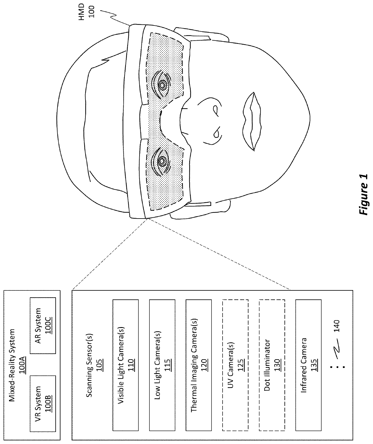
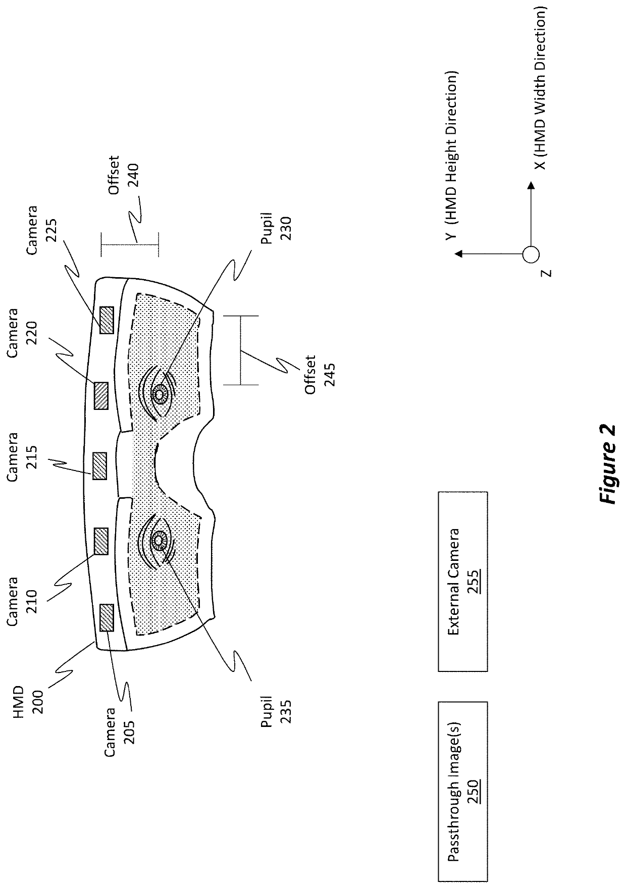
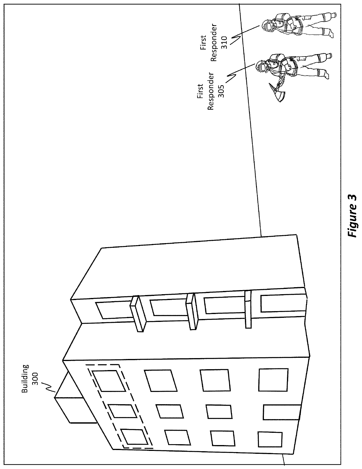
[0035]Embodiments disclosed herein relate to systems, devices (e.g., wearable devices, hardware storage devices, etc.), and methods that update a position of overlaid image content using inertial measurement unit (IMU) data to reflect subsequent changes in camera positions to minimize latency effects. As used herein, a “system camera” refers to an integrated camera that is a part of an HMD. An “external camera” is a camera that is detached from or that is separated from the HMD. An example of an external camera can be a camera mounted on a tool used by a user who is also wearing an HMD.

[0036]In some embodiments, a system camera and an external camera generate images. These images are overlaid on one another and aligned to form an overlaid image. Content from the external camera image is surrounded by a bounding element in the overlaid image. IMU data associated with both the system camera and the external camera is obtained. Based on that IMU data, the embodiments determine an amoun...


PUM


Abstract

Techniques for updating a position of overlaid image content using IMU data to reflect subsequent changes in camera positions to minimize latency effects are disclosed. A “system camera” refers to an integrated camera that is a part of an HMD. An “external camera” is a camera that is separated from the HMD. The system camera and the external camera generate images. These images are overlaid on one another and aligned to form an overlaid image. Content from the external camera image is surrounded by a bounding element in the overlaid image. IMU data associated with both the system camera and the external camera is obtained. Based on that IMU data, an amount of movement that the system camera and/or the external camera have moved since the images were originally generated is determined. Based on that movement, the bounding element is shifted to a new position in the overlaid image.

Description

BACKGROUND[0001]Mixed-reality (MR) systems, including virtual-reality (VR) and augmented-reality (AR) systems, have received significant attention because of their ability to create truly unique experiences for their users. For reference, conventional VR systems create completely immersive experiences by restricting their users' views to only virtual environments. This is often achieved through the use of a head-mounted device (HMD) that completely blocks any view of the real world. As a result, a user is entirely immersed within the virtual environment. In contrast, conventional AR systems create an augmented-reality experience by visually presenting virtual objects that are placed in or that interact with the real world.[0002]As used herein, VR and AR systems are described and referenced interchangeably. Unless stated otherwise, the descriptions herein apply equally to all types of MR systems, which (as detailed above) include AR systems, VR reality systems, and / or any other simil...

Claims


Application Information

Patent Timeline
Patent Type & Authority Applications(United States)
IPC IPC(8): G02B27/01G06T19/00G06T7/246G06T7/33G06F3/01
CPCG02B27/0172G06T19/006G06T7/248G02B2027/0138G06F3/012G06F3/017G06T7/337H04N5/272G02B27/017H04N23/80H04N23/63H04N23/90
Inventor BLEYER, MICHAELSINHA, SUDIPTA NARAYANEDMONDS, CHRISTOPHER DOUGLASPRICE, RAYMOND KIRK
Owner MICROSOFT TECH LICENSING LLC
Why Eureka
Try Eureka