Vehicle control system controlling exertion of braking force on wheel

a technology of vehicle control system and braking force, which is applied in the direction of braking system, analogue process for specific applications, instruments, etc., can solve problems such as sudden deceleration unanticipated by the vehicle driver

Active Publication Date: 2014-09-30
DENSO CORP
View PDF18 Cites 5 Cited by
  • Summary
  • Abstract
  • Description
  • Claims
  • Application Information

AI Technical Summary

Benefits of technology

[0009]It is another object of the invention to provide a vehicle control system which is designed to apply braking force to wheels of a vehicle when being at a stop and works as a braking controller to minimize or avoid sudden deceleration unexpected by a vehicle driver.

Problems solved by technology

At this time when the real speed does not yet become zero (0), the application of the first braking force to the wheel may result in sudden deceleration unanticipated by a vehicle driver.

Method used


Image

  • Vehicle control system controlling exertion of braking force on wheel
  • Vehicle control system controlling exertion of braking force on wheel
  • Vehicle control system controlling exertion of braking force on wheel

Examples


Embodiment Construction

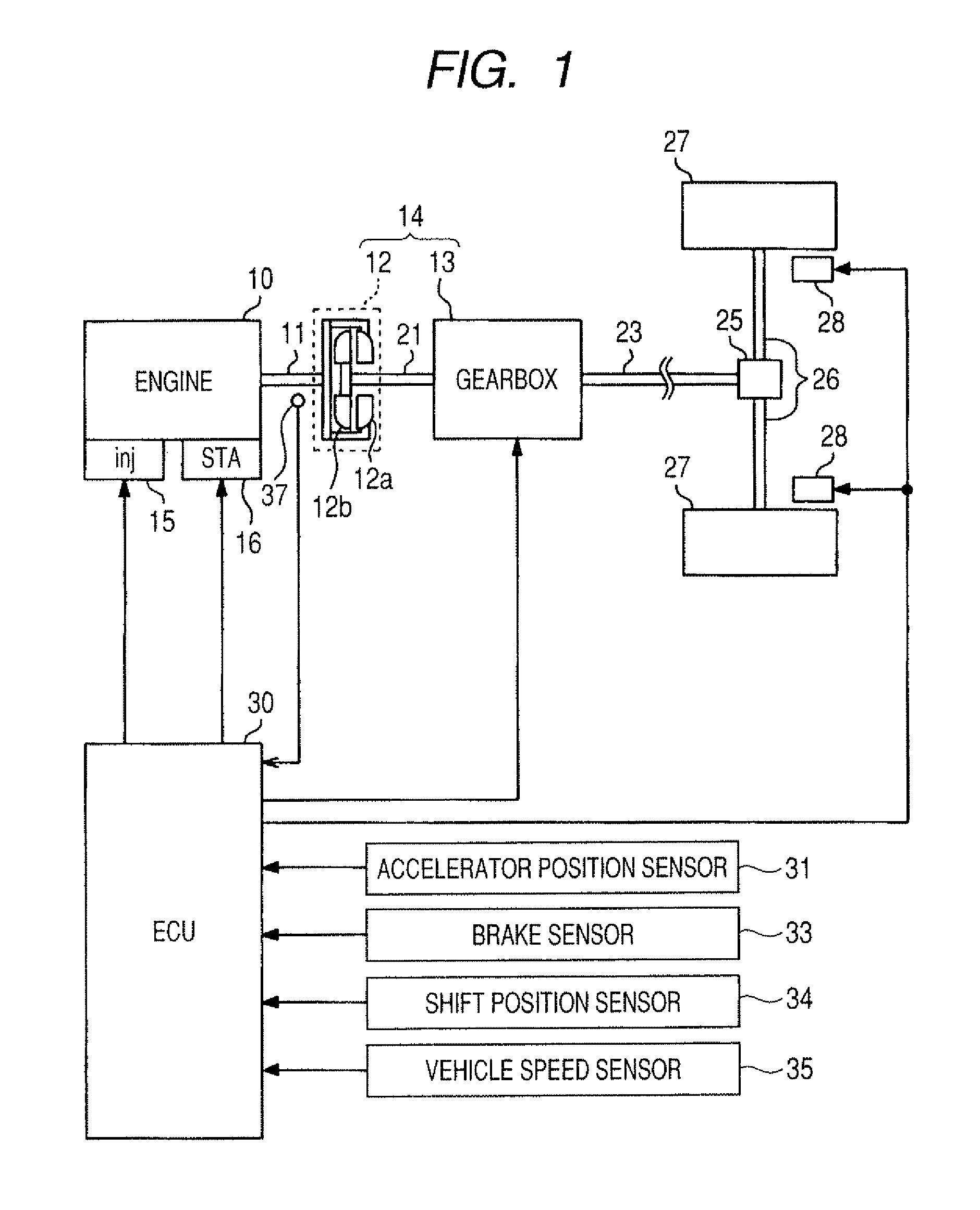
[0030]Referring to the drawings, particularly to FIG. 1, there is shown a vehicle control system according to the invention which is installed in an automotive vehicle equipped with an engine 10 and an automatic transmission 14.

[0031]The automatic transmission 14 includes a torque converter 12 and a gearbox 13. The gearbox 13 is coupled to the crankshaft 11 (i.e., an output shaft) of the engine 10 through the torque converter 12. The engine 10 is, for example, a multi-cylinder gasoline engine and equipped with injectors 15 and spark plugs, one for each cylinder thereof. The engine 10 has installed thereon a starter 16 to crank or give initial rotation to the engine 10 when it is required to start the engine 10. The engine 10 may alternatively be a diesel engine.

[0032]The torque converter 12 is made up of a pump impeller 12a coupled to the crankshaft 11, a turbine impeller 12b coupled to an input shaft 21 of the gearbox 13, and a one-way clutch, etc. The turbine impeller 12b rotates ...


PUM


Abstract

A vehicle control system is provided which is designed to stop or restart an engine automatically. The system is equipped with a vehicle speed determining circuit which determines the speed of the vehicle and has a dead zone around where a real speed of the vehicle is zero. The vehicle speed determining circuit has a characteristic in which when falling in the dead zone, the determined speed shows zero. When the determined speed is zero, and the real speed is expected to have dropped to zero, the system applies a first braking force to the wheel to keep the vehicle stopped. When the determined speed has become zero following the automatic stop of the engine, the system applies a second braking force smaller in magnitude than the first braking force to the wheel, thereby decelerating the vehicle slowly to avoid unexpected sudden deceleration.

Description

CROSS REFERENCE TO RELATED DOCUMENT[0001]The present application claims the benefit of Japanese Patent Application No. 2009-50118 filed on Mar. 4, 2009, the disclosure of which is incorporated herein by reference.BACKGROUND OF THE INVENTION[0002]1. Technical Field of the Invention[0003]The present invention relates generally to a vehicle control system designed to control exertion of braking force on wheels of a vehicle when being at a stop.[0004]2. Background Art[0005]Japanese Patent First Publication No. 2008-44443 discloses a vehicle control system equipped with a hill holder device working to prevent the vehicle from accidentally rolling backward when the driver starts the vehicle on steep hills. This system is designed to keep the hydraulic braking pressure at a high level to apply the braking force to wheels of the vehicle when three conditions are all met: an inclination of the road surface is greater than a given value, the brake pedal of the vehicle is being depressed, and ...

Claims


Application Information

Patent Timeline
Patent Type & Authority Patents(United States)
IPC IPC(8): B60T7/00B60T7/12
CPCB60T7/12
Inventor SAITO, TATSUYA
Owner DENSO CORP
Why Eureka
Try Eureka