Rear lateral sensing system and method of vehicle

a rear lateral sensing and vehicle technology, applied in vehicle components, control devices, instruments, etc., can solve the problem of inaccurate generation of warning signals against the target vehicle entering the warning area, and achieve the effect of accurate warning and accurate determination

Pending Publication Date: 2022-06-16
HYUNDAI MOBIS CO LTD
View PDF0 Cites 0 Cited by
  • Summary
  • Abstract
  • Description
  • Claims
  • Application Information

AI Technical Summary

Benefits of technology

[0008]The present disclosure is proposed to solve the problems described above, and an object of the present disclosure is to provide a system and a method of rear lateral sensing of a vehicle for providing an accurate warning signal by transmitting the warning signal against an obstacle when the obstacle is present on the rear lateral side of the vehicle and accurately determining whether the obstacle completely exits from a warning area.
[0009]In order to achieve the object described above, the rear lateral sensing system of the vehicle according to the present disclosure includes at least one sensor setting a monitoring area in a rear or on a rear lateral side of the vehicle and detecting an obstacle; a warning transmission device generating a warning signal when the at least one sensor detects the obstacle; a determination device calculating a generation time of the warning signal according to a tracked location of the obstacle; and a controller setting a determination target according to the tracked location of the obstacle, setting a determination area in the monitoring area based on the tracked location of the obstacle, and causing the determination device to adjust the generation time of the warning signal to last longer when the determination target is located in the determination area.
[0025]The rear lateral sensing system and method structured as described above provide an accurate warning signal by transmitting the warning signal against the obstacle when the obstacle is present on the rear lateral side of the vehicle and accurately determining whether the obstacle completely exits from the warning area.

Problems solved by technology

However, the conventional RCTA targets the front portion of the target vehicle such that the warning signal is turned off even when the target vehicle has not completely passed by.
In addition, presence of other vehicles or obstacles are in the vicinity of the vehicle interferes with the identification of the target vehicle in the monitoring area so that a warning signal against the target vehicle entering the warning area may not be accurately generated.

Method used


Image

  • Rear lateral sensing system and method of vehicle
  • Rear lateral sensing system and method of vehicle
  • Rear lateral sensing system and method of vehicle

Examples


Embodiment Construction

[0030]A system and a method of rear lateral sensing of a vehicle according to a preferred embodiment of the present disclosure will be described with reference to the accompanying diagrams in the following.

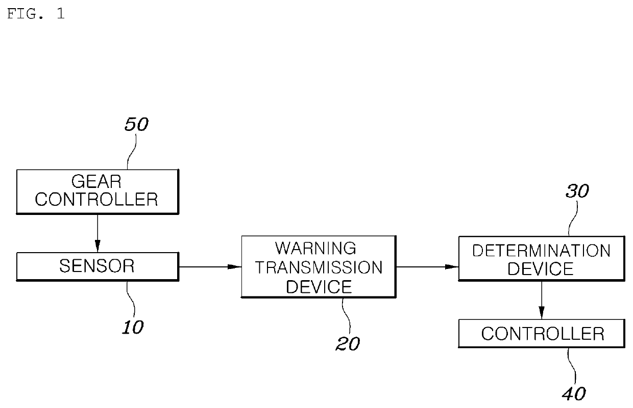
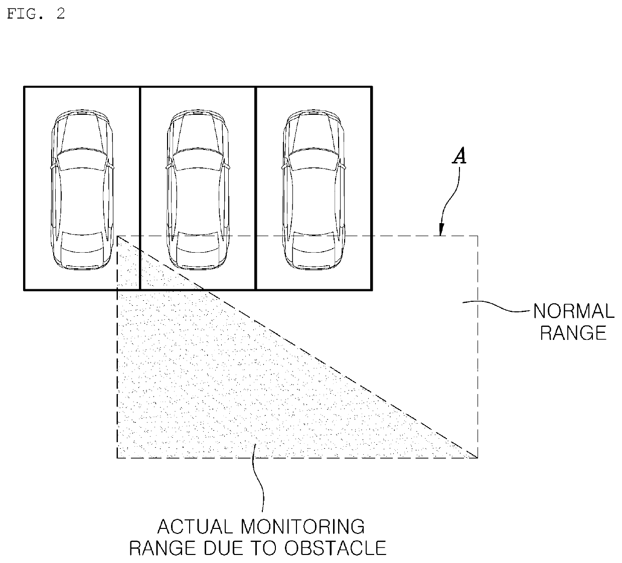
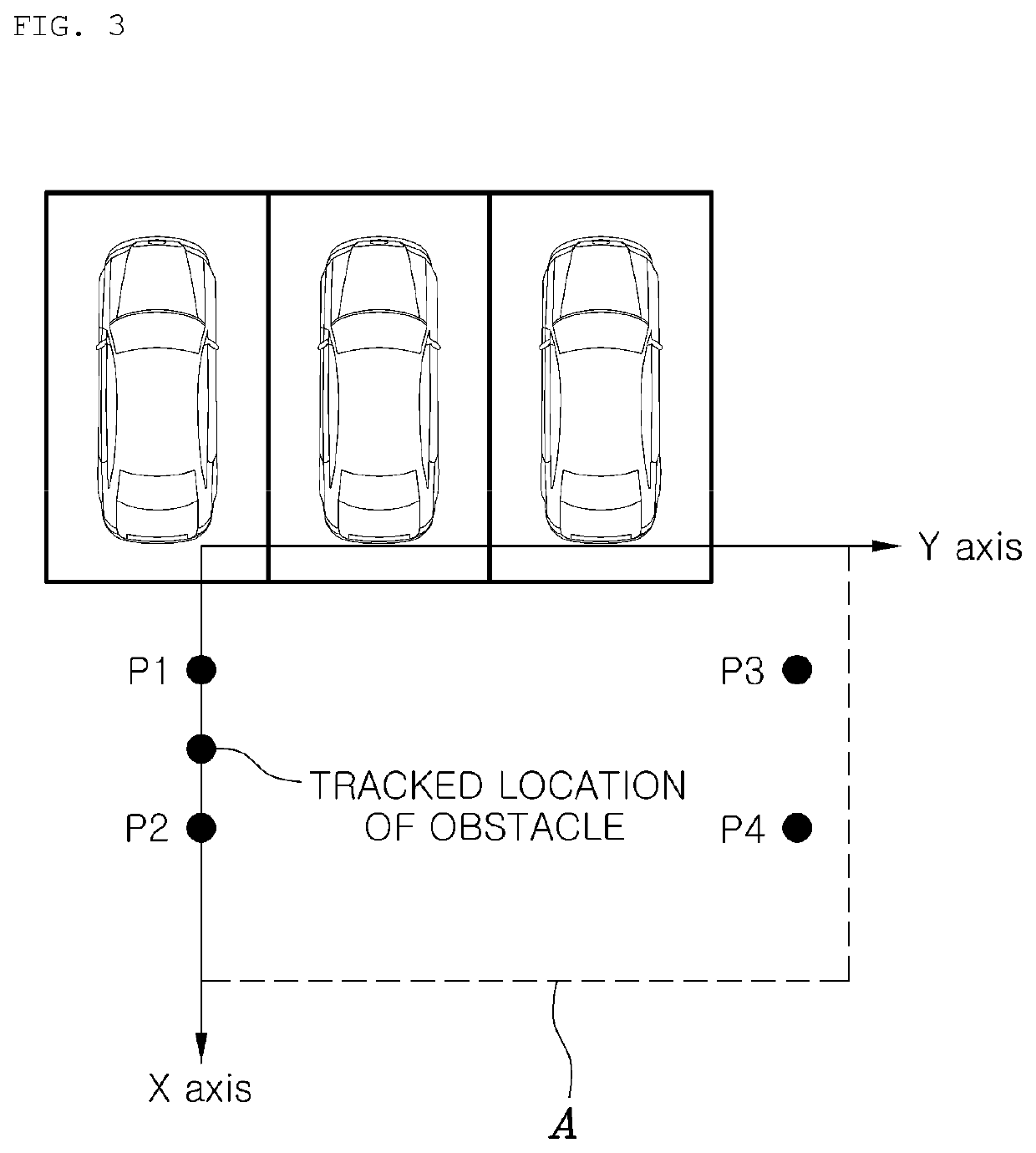
[0031]FIG. 1 is a block diagram of a rear lateral sensing system of a vehicle according to the present disclosure, FIGS. 2 to 5 are diagrams for describing the rear lateral sensing system of the vehicle shown in FIG. 1, and FIG. 6 is a flowchart of a rear lateral sensing method according to the present disclosure.

[0032]As shown in FIG. 1, the rear lateral sensing system of the vehicle according to the present disclosure includes at least one sensor 10 setting a monitoring area A in the rear or on a rear lateral side of the vehicle and detecting an obstacle; a warning transmission device 20 generating a warning signal when the sensor 10 detects the obstacle; a determination device 30 calculating a generation time of the warning signal according to a tracked location of the obstacle...


PUM


Abstract

The present disclosure discloses a system and a method of rear lateral sensing of a vehicle for providing an accurate warning signal by transmitting a warning signal against an obstacle when the obstacle is present on a rear lateral side of the vehicle and accurately determining whether the obstacle completely exits from a warning area.

Description

CROSS REFERENCE TO RELATED APPLICATION[0001]The present application claims priority to Korean Patent Application No. 10-2020-0176771, filed Dec. 16, 2020, the entire contents of which is incorporated herein for all purposes by this reference.BACKGROUNDTechnical Field[0002]The present disclosure relates to a system and a method of rear lateral sensing of a vehicle for detecting a target vehicle entering the rear lateral side of the vehicle and transmitting a warning signal.Description of the Related Art[0003]The rear lateral warning system of the vehicle is a system for warning a driver when it is determined while the vehicle is driving that an obstacle is present in a blind spot located on the rear lateral side or that there is a risk of collision in the event of a lane change to the right or left with a vehicle approaching from behind at a high speed, thereby improving the convenience of the driver.[0004]Specifically, such a rear lateral warning system includes a blind spot detecti...

Claims


Application Information

Patent Timeline
Patent Type & Authority Applications(United States)
IPC IPC(8): B60W50/14B60W30/18B60W30/095
CPCB60W50/14B60W30/18036B60W2420/42B60W2050/146B60W2554/4045B60W30/095B60Q9/008G08G1/166G08G1/168B60W30/08B60W10/10B60R21/0134B60W2050/143B60W2552/50B60Y2300/08
Inventor KANG, EUN SEOK
Owner HYUNDAI MOBIS CO LTD
Why Eureka
Try Eureka