Tensioning device for a drive train

a technology of a tensioning device and a drive train, which is applied in the direction of wing accessories, mechanical equipment, gearing, etc., can solve the problems of difficult access, inconvenient adjustment of the tensioning device, and noise generation

Pending Publication Date: 2022-07-28
AUTOMATIC TECH AUSTRALIA
View PDF8 Cites 0 Cited by
  • Summary
  • Abstract
  • Description
  • Claims
  • Application Information

AI Technical Summary

Problems solved by technology

Over time, continued movement of the trolley back and forth along the track during door opening and closing operations can lead to a slackening in the belt or chain through wear, leading to excessive movement of components of the drive train, thereby creating noise and possibly causing dam...

Method used


Image

  • Tensioning device for a drive train
  • Tensioning device for a drive train
  • Tensioning device for a drive train

Examples


Embodiment Construction

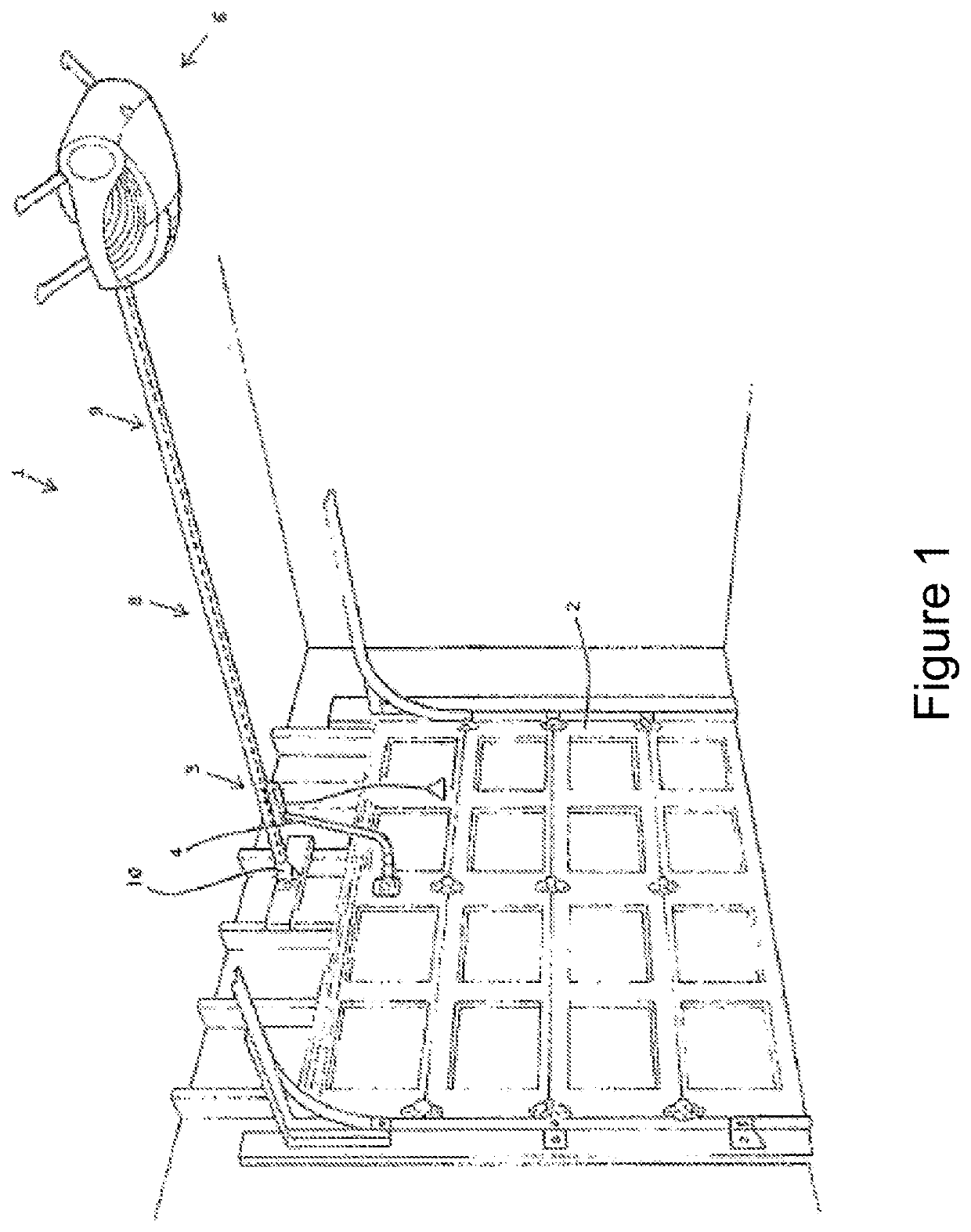
[0028]FIG. 1 illustrates a door operating system 1 installed in a garage to drive a door 2 between open and closed positions. A closure arm 4 connects the door 2 to a closure drive assembly. The closure drive assembly includes a motor operator 6. The motor of operator 6 is arranged to drive a longitudinal drive member in the form of a drive belt 8, arranged in a closed loop arrangement within or around a track 9, which extends between the door 2 and the operator 6. A drive device for the closure drive assembly in the form of trolley 3 moves along the track 9 and is connected to the closure arm 4. Mounted above the door 2 and received at the door end of track 9 is a belt tensioner 10. The belt tensioner 10 is configured to receive the belt 8 and allow a user to set and adjust the level of tension in the belt 8.

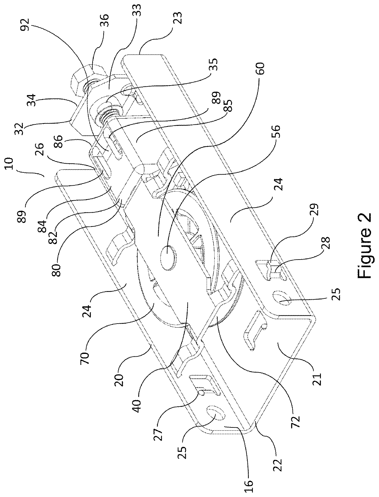
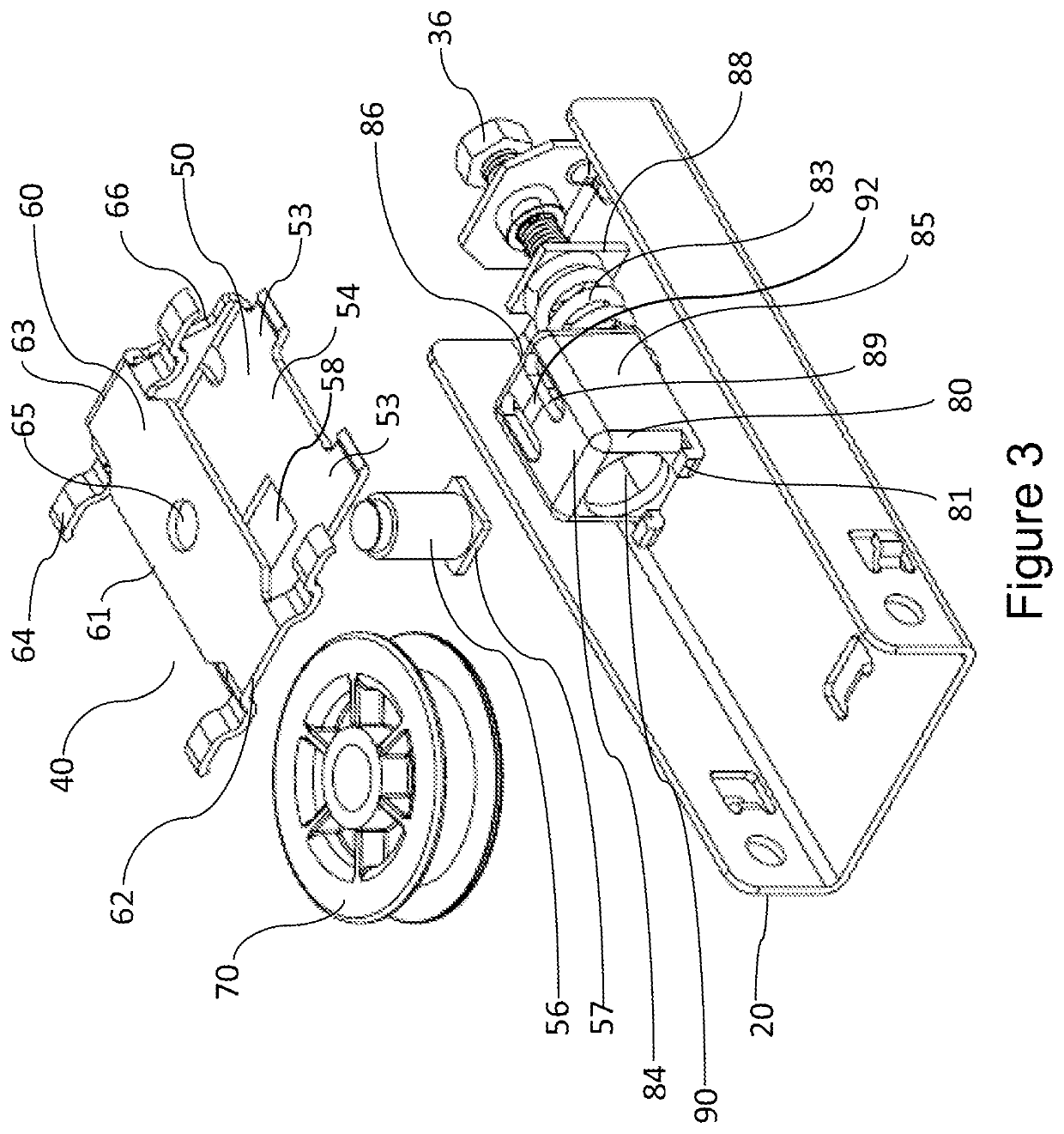
[0029]FIGS. 2 and 3 illustrate a belt tensioner 10 in accordance with an embodiment of the present invention. It will be appreciated that FIGS. 2 and 3 illustrate a view from a...


PUM


Abstract

A tensioning device for a door operating system includes a pulley carriage on which a pulley of the door operating system is mounted for rotation, the pulley carriage being movable relative to a track of the door operating system. The tensioning device further includes an adjuster configured to move the pulley carriage relative to the track and thereby alter a level of tension in a longitudinal drive component of the door operating system, the adjuster of the tensioning device being accessible from an end of the tensioning device facing a track operator end of the door operating system. The tensioning device also includes a resilient member operatively engaged with the adjuster, the resilient member configured to provide damping of forces experienced by the longitudinal drive component.

Description

FIELD OF THE INVENTION[0001]The present invention generally relates to a tensioning device used in the drive train of a door opening system.BACKGROUND OF THE INVENTION[0002]The use of tensioning devices with a drive train are generally well known. One area of application for a tensioning device is part of a drive train for a door operating system, such as for a garage sectional door. The door is generally moved between open and closed positions by a door operator, which drives a belt or chain that is attached to a trolley that runs forward and backward along a track or rail mounted to the garage ceiling, with the trolley attached to the door via a closure arm. Over time, continued movement of the trolley back and forth along the track during door opening and closing operations can lead to a slackening in the belt or chain through wear, leading to excessive movement of components of the drive train, thereby creating noise and possibly causing damage.[0003]When the above issue is enco...

Claims


Application Information

Patent Timeline
IPC IPC(8): E05F15/686
CPCE05F15/686E05Y2201/474E05Y2201/652E05Y2900/132E05Y2201/672E05Y2201/64E05Y2900/106E05Y2201/668F16H7/08E05D13/1269E05F15/684E06B2003/7044E05Y2201/492F16H2007/0865F16H2007/0891F16H7/12F16H7/1263
Inventor HAWKINS, RAYMONDMATTHEWS, GEORGE
Owner AUTOMATIC TECH AUSTRALIA
Why Eureka
Try Eureka