Compressor, compressor assembly, and method of assembling compressor

Pending Publication Date: 2022-08-04
MITSUBISHI HEAVY INDUSTIES COMPRESSOR CORP
View PDF8 Cites 0 Cited by
  • Summary
  • Abstract
  • Description
  • Claims
  • Application Information

AI Technical Summary

Benefits of technology

The present invention provides a compressor, compressor assembly, and method of assembling a compressor that allows for easy and reliable insertion of a bundle into a casing with an opening portion at the lower part. This provides a more efficient and reliable operation of the compressor.

Problems solved by technology

In the configuration disclosed in Japanese Patent No. 6521392, when an attempt is made to insert the bundle into the casing having such an opening portion, there is a case where the side roller or the intermediate support portion interferes with the opening, making it difficult to insert the bundle.

Method used


Image

  • Compressor, compressor assembly, and method of assembling compressor
  • Compressor, compressor assembly, and method of assembling compressor
  • Compressor, compressor assembly, and method of assembling compressor

Examples


Embodiment Construction

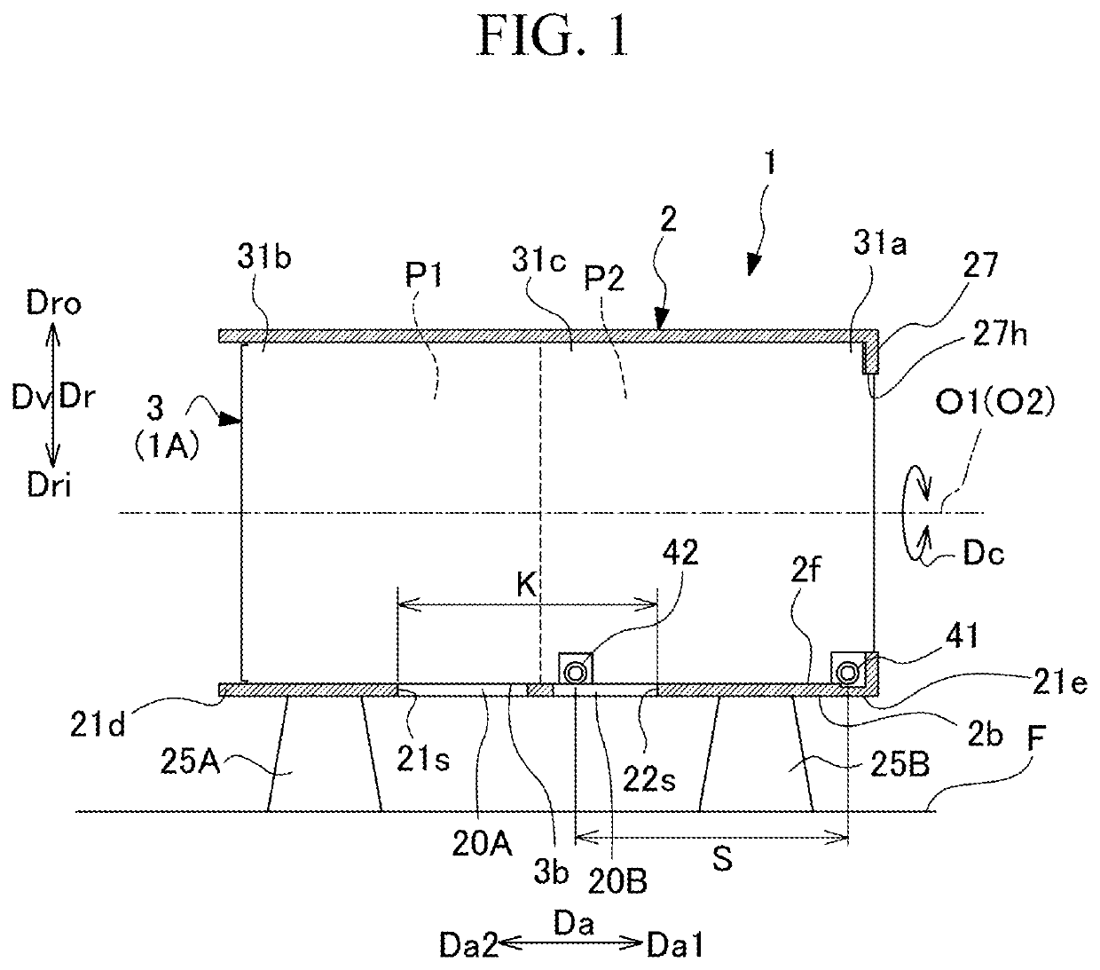
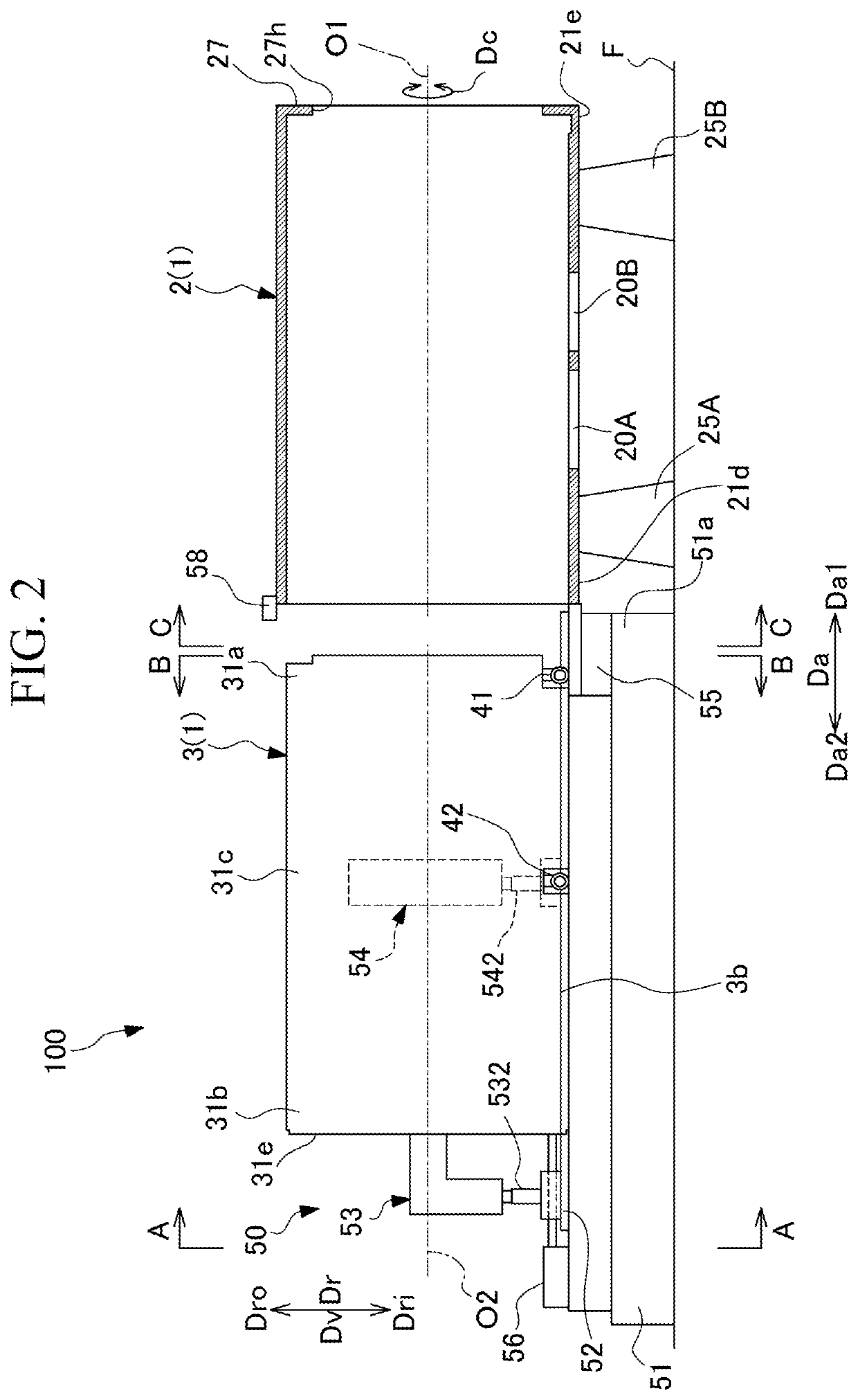
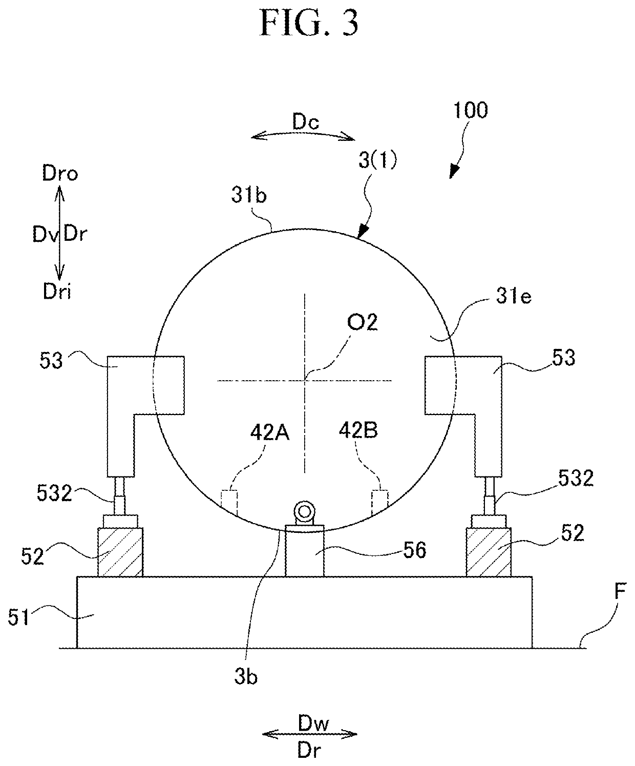
[0024]Hereinafter, a mode for carrying out a compressor, a compressor assembly, and a method of assembling a compressor according to the present disclosure will be described with reference to the accompanying drawings. However, the present disclosure is not limited to this embodiment.

[0025](Configuration of Compressor)

[0026]As shown in FIG. 1, a compressor 1 mainly includes a casing 2, a bundle 3, a first roller 41, and a second roller 42. The compressor 1 is a uniaxial multi-stage type centrifugal compressor that compresses and discharges a working fluid supplied to the inside. The compressor 1 of the present embodiment has a first compression unit P1 and a second compression unit P2 for compressing the working fluid on a second side Da2 in an axial direction Da and a first side Da1 in the axial direction Da, respectively. The compressor 1 is a so-called back-to-back type in which the first compression unit P1 and the second compression unit P2 are symmetrically provided in the axi...


PUM


Abstract

A compressor includes: a casing that is formed in a cylindrical shape and has an opening portion that makes an inside and an outside of the casing communicate with each other at a lower portion in a vertical direction; a bundle that is accommodated inside the casing in a state of being insertable and removable in the axial direction; a first roller that is disposed at an end portion of a lower portion of the bundle and comes into contact with an inner peripheral surface of a lower portion of the casing; and a second roller that is disposed at the lower portion of the bundle at an interval from the first roller, and comes into contact with the inner peripheral surface of the lower portion of the casing.

Description

BACKGROUND OF THE INVENTIONField of the Invention[0001]The present disclosure relates to a compressor, a compressor assembly, and a method of assembling a compressor.[0002]Priority is claimed on Japanese Patent Application No. 2021-015854, filed on Feb. 3, 2021, the content of which is incorporated herein by reference.Description of Related Art[0003]In Japanese Patent No. 6521392, there is disclosed a configuration in which when inserting a bundle into a casing of a compressor, a side roller provided at a leading end portion of the bundle, an end portion support portion that supports a rear end portion of the bundle, and a pair of intermediate support portions that support an intermediate portion of the bundle are provided. In such a configuration, the bundle is inserted into the casing by moving the side roller, the end portion support portion, and the intermediate support portions along a rail disposed outside the casing and the inner peripheral surface of the casing.SUMMARY OF TH...

Claims


Application Information

Patent Timeline
IPC IPC(8): F04D29/42F04D17/10
CPCF04D29/4206F04D17/10F04D29/624F04D17/12
Inventor OKA, HIROAKIKOYANAGI, JUN
Owner MITSUBISHI HEAVY INDUSTIES COMPRESSOR CORP
Why Eureka
Try Eureka