Apparatus and method for applying in an automatic way foam elements on a die cutter

a technology of automatic application and die cutter, which is applied in the direction of manipulators, gripping heads, program-controlled manipulators, etc., can solve the problems of reducing the length of the ejection rubber elements too much, time-consuming and tricky operation of the rubber coating of the die-cutter, and the pattern of cutting and creasing rules

Pending Publication Date: 2022-09-15
PROFORM
View PDF0 Cites 1 Cited by
  • Summary
  • Abstract
  • Description
  • Claims
  • Application Information

AI Technical Summary

Benefits of technology

The objective of the invention is to provide a device and technique for applying a rubber coating to a die-cutter in a straightforward, time-consuming, and efficient way, with the aid of minimal human labor and rubber amounts.

Problems solved by technology

The rubber coating of the die-cutter is a time-consuming and tricky operation, which must be carried out by experienced people; it is therefore desirable to make the rubber coating as fast as possible.
A further limitation of the known art is that the length of the ejection rubber elements cannot be reduced too much, because beyond a certain limit a human being would no longer be able to distinguish one shape from another.
The need to work with ejection rubber elements having a minimum length that allows the worker to correctly identify them, means that the pattern of the cutting and creasing rules, which can also define acute angles or curved sections, cannot always be followed in an optimal way and often involves a considerable amount of waste.

Method used


Image

  • Apparatus and method for applying in an automatic way foam elements on a die cutter
  • Apparatus and method for applying in an automatic way foam elements on a die cutter
  • Apparatus and method for applying in an automatic way foam elements on a die cutter

Examples


Embodiment Construction

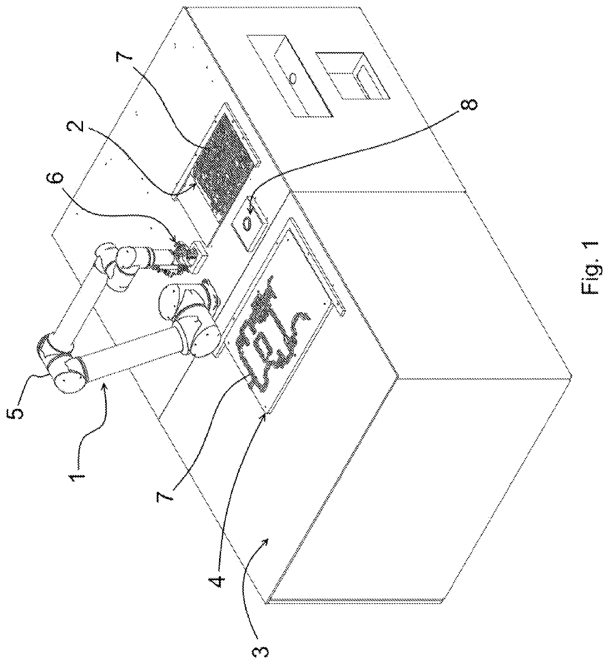
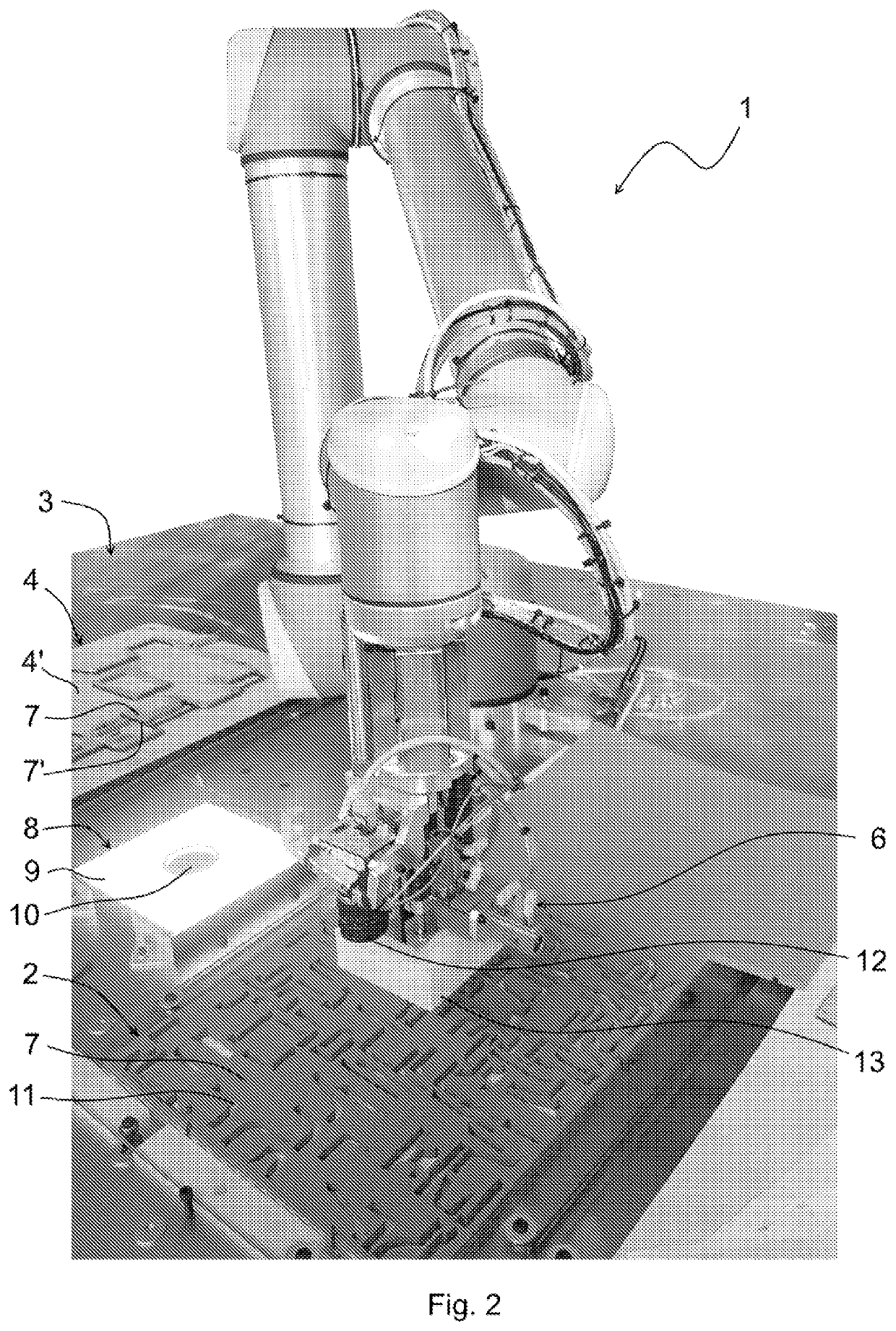
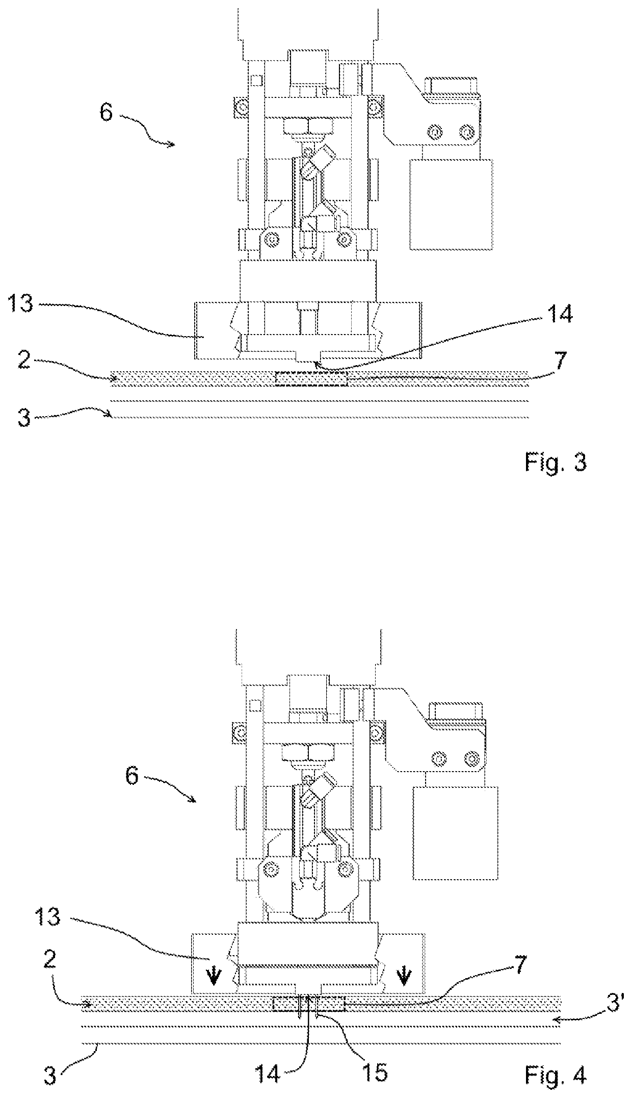
[0064]Referring to FIGS. 1-7 the number 1 generally denotes an apparatus according to the present invention, which involves the whole rubber coating process of the die-cutters starting from pre-cut rubber sheets 2, on which multiple ejection elements are defined. The apparatus 1 carries out the positioning of each ejection rubber element on the die-cutter, in the univocally corresponding position, in turn imposed by the scheme of the cutting rules and creasing rules that are on the die-cutter.

[0065]The apparatus 1 is arranged on a working plane 3, for example having dimensions of 2000×1600 mm, in order to process die-cutters 4 with dimensions up to 1600×1100 mm. The apparatus comprises a manipulator 5, which in the model shown in the figures is an anthropomorphic arm, at whose end a gripper 6 specially designed for withdrawing and positioning ejection rubber elements 7 from the sheet 2 and for positioning the latter on the die-cutter 4, in particular on the support of the die-cutter...


PUM


Abstract

An apparatus and a method for automatically applying, without the intervention of an operator, rubber elements on a die-cutter during the manufacturing step thereof, are described. The apparatus comprises a manipulator, preferably a robotic arm, and a needle gripper. The gripper withdraws the water jet pre-cut rubber elements from a sheet with double-sided adhesive tape, and places them one by one at the point provided for by the working program.

Description

FIELD OF THE INVENTION[0001]The present invention refers to an apparatus and a method for automatically applying, without the intervention of an operator, rubber elements on a die-cutter during the manufacturing step thereof.STATE OF THE ART[0002]Die cutting is a process known and very popular in several fields of the art, such as paper processing industry and typography. It is used to obtain, by cutting, pieces with a predetermined shape, sometimes even very complex, from a sheet or band of a relatively soft material, such as paper, cardboard, fabric, leather, metal sheet, some types of plastics.[0003]Die cutting machines fundamentally comprise two components adapted to pressure cooperate together to cut die-cut elements from sheets or bands of material: the die cutter and the counter-die cutter.[0004]The die cutter is formed by a flat or cylindrical support comprising a plurality of cutting rules (i.e. metal blades) provided with an active cutting edge. The cutting rules are canti...

Claims


Application Information

Patent Timeline
Patent Type & Authority Applications(United States)
IPC IPC(8): B26F1/44B26F1/24B26D5/00B25J9/16B25J15/00
CPCB26F1/44B26F1/24B26D5/007B25J9/1697B25J15/0071B26F2001/4463B26D7/1818B26D7/1836B25J19/023
Inventor ROSSINI, ALBERTO LUIGIMILIC, ZIVOTA
Owner PROFORM
Why Eureka
Try Eureka