Emblem Member

a technology of emblem members and emblems, applied in the field of emblem members, can solve the problems of not providing a the difficulty of significant change of emblem members in terms of shape, and achieve the effect of large degree of design freedom

Pending Publication Date: 2022-10-06
MIZUNO CORPORATION
View PDF3 Cites 0 Cited by
  • Summary
  • Abstract
  • Description
  • Claims
  • Application Information

AI Technical Summary

Benefits of technology

[0005]The present disclosure has been made in order to address such an issue as above, and an object of the present disclosure is to provide an emblem member having a large degree of freedom in design.

Problems solved by technology

In the above-described conventional method, it is difficult to significantly change the emblem member in terms of shape, tactile impression and the like, and there is a problem in that the method does not provide a large degree of freedom in design.

Method used


Image

  • Emblem Member
  • Emblem Member
  • Emblem Member

Examples


Embodiment Construction

[0029]Hereinafter, an embodiment of the present disclosure will be described. Identical components are identically denoted and will not be described repeatedly.

[0030]

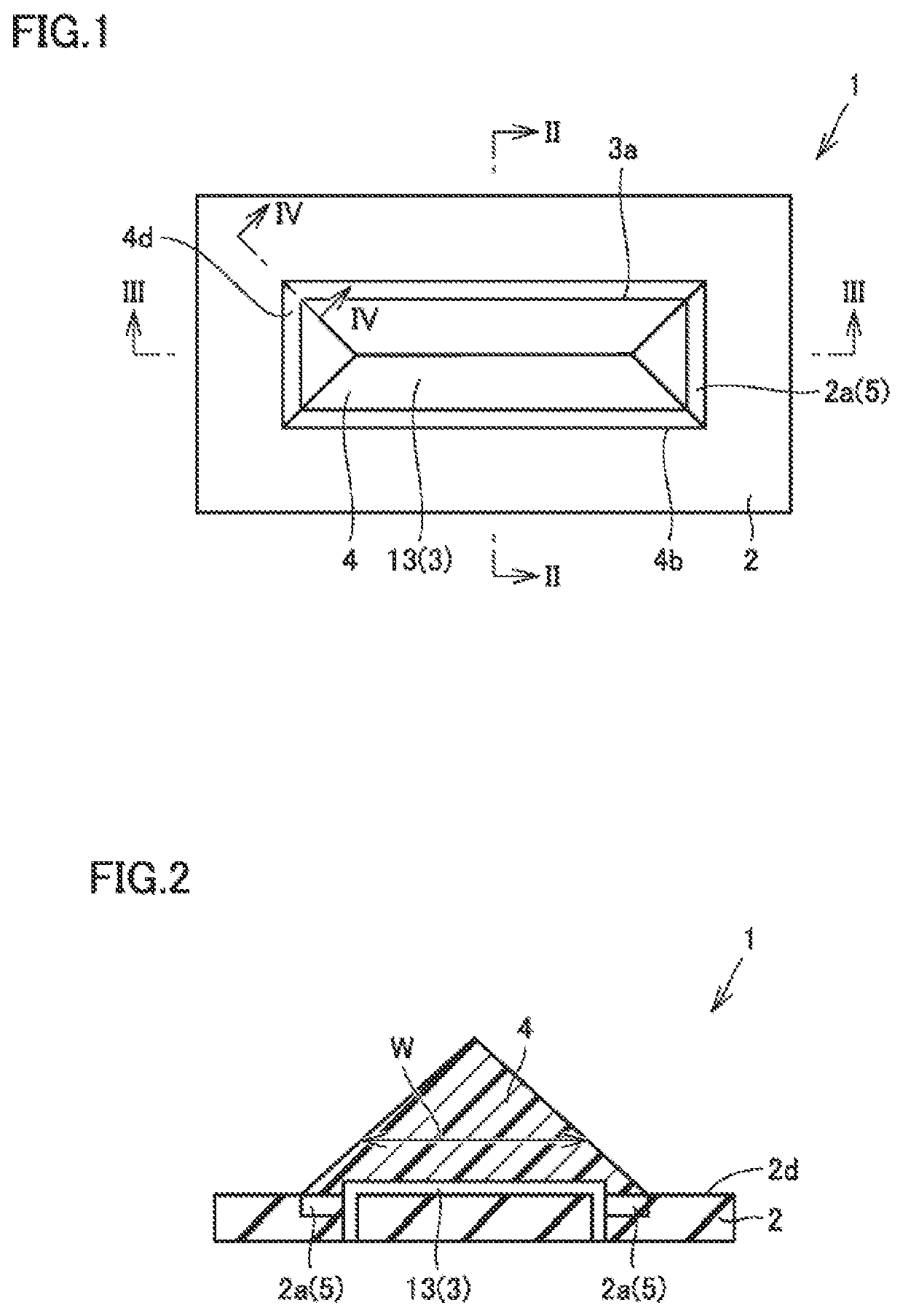
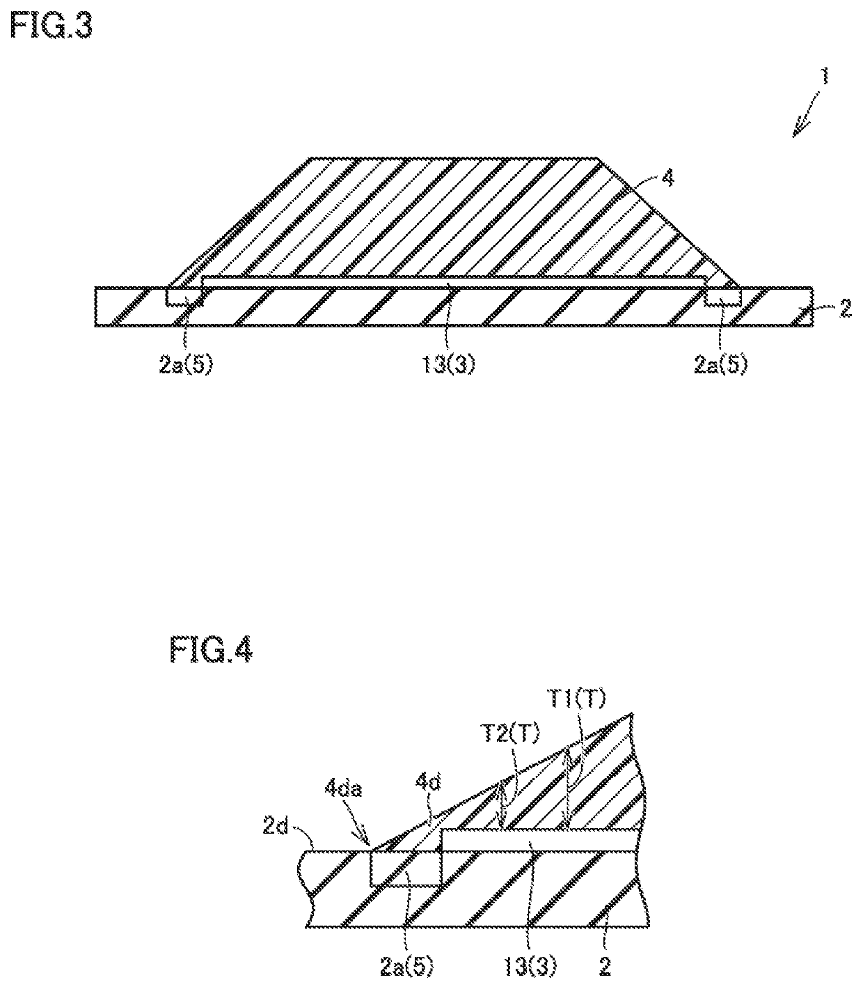
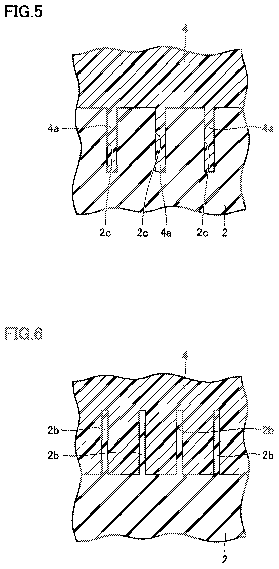
[0031]FIG. 1 is a schematic plan view of an emblem member according to an embodiment. FIG. 2 is a schematic cross section taken along a line II-II indicated in FIG. 1. FIG. 3 is a schematic cross section taken along a line indicated in FIG. 1. FIG. 4 is a schematic cross section taken along a line IV-IV indicated in FIG. 1. FIG. 5 is a schematic diagram for illustrating a configuration of a connecting portion of the emblem member of FIG. 1. FIG. 6 is a schematic diagram for illustrating an exemplary variation of the connecting portion in the emblem member of FIG. 1. FIG. 7 is a schematic cross section of a yarn of embroidery forming a mark portion in the emblem member of FIG. 1. FIG. 8 is a schematic cross section showing an exemplary variation of the yarn of the embroidery forming the mark portion in the emblem member ...


PUM


Abstract

An emblem member having a large degree of freedom in design can be obtained. The emblem member comprises a base portion, a mark portion, and a transparent member. The base portion has a surface. The mark portion is formed on a surface of the base portion. The transparent member is connected to the base portion so as to cover at least a portion of the mark portion. In this case, the mark portion can be visually recognized through the transparent member, and the transparent member can have a three-dimensional shape determined independently of the shape and material(s) of the mark portion. This can provide an increased degree of freedom in designing the emblem member.

Description

[0001]This nonprovisional application is based on Japanese Patent Application No. 2021-063549 filed on Apr. 2, 2021 with the Japan Patent Office, the entire contents of which are hereby incorporated by reference.BACKGROUND OF THE INVENTIONField of the Invention[0002]The present disclosure relates to an emblem member.Description of the Background Art[0003]A conventionally known method employs three-dimensional embroidery in order to form a three-dimensional emblem member (for example, see Japanese Patent Laying-Open No. 3-249259). Japanese Patent Laying-Open No. 3-249259 discloses that a three-dimensional embroidery pattern is formed by introducing an elastic body inside a yarn constituting the embroidery pattern.SUMMARY OF THE INVENTION[0004]In the above-described conventional method, it is difficult to significantly change the emblem member in terms of shape, tactile impression and the like, and there is a problem in that the method does not provide a large degree of freedom in des...

Claims


Application Information

Patent Timeline
Patent Type & Authority Applications(United States)
IPC IPC(8): D05C17/00
CPCD05C17/00D10B2507/00A63B71/143A63B2071/0694A63B2102/18A63B2102/182B32B3/08B32B27/06B32B2451/00
Inventor KOBAYASHI, MASATAKANISHIMURA, TOSHIAKITAN, JOJI
Owner MIZUNO CORPORATION
Why Eureka
Try Eureka