Ink tank for ink jet recording device

a technology of ink jet recording device and ink tank, which is applied in printing and other directions, can solve the problems of ink being unable to be easily dried, ink being unable to be smoothly discharged from the ink jet recording head, and insufficient ink being dried on paper, etc., and achieves excellent resource protection property, large degree of freedom in design, and stable application of negative pressure on ink

Inactive Publication Date: 2007-11-29
CANON KK
View PDF17 Cites 3 Cited by
  • Summary
  • Abstract
  • Description
  • Claims
  • Application Information

AI Technical Summary

Benefits of technology

[0017]An object of the present invention is to provide an ink tank capable of inhibiting penetration of a gas even in an ink storage section made of a resin, having such a flexibility as to stably apply a negative pressure to ink, having an excellent resource protective property and applicable even to a small and inexpensive ink jet recording device having a large degree of freedom in design.

Problems solved by technology

In addition, viscosity increases, and the ink is not smoothly discharged from the ink jet recording head.
When an image is output with the ink having its properties changed in this manner, a long time is required for drying the ink attached to paper, and the ink migrates.
As a result, problems such as color mixture and deterioration of a resolution of the image occur in some case.
However, in the ink storage section of the bag made of such a plastic, the gas penetrates the resin.
When the ink is volatilized or consumed, outside air invades an inner space of the storage section to cause a problem.
As a result, it is difficult to reduce a capacity of the ink storage section with the consumption of the ink.
There is a problem that all the stored ink cannot be used.
Since the ink bag formed of the laminated film has a high mechanical rigidity, it is difficult to adjust the capacity of the ink bag with the consumption of the ink.
As a result, the negative pressure applied to the ink tends to be unstable.
Furthermore, it is difficult to sort the laminated film during disposal of the film as garbage.
Therefore, there is a problem of resource protection.

Method used


Image

  • Ink tank for ink jet recording device
  • Ink tank for ink jet recording device
  • Ink tank for ink jet recording device

Examples


embodiment 1

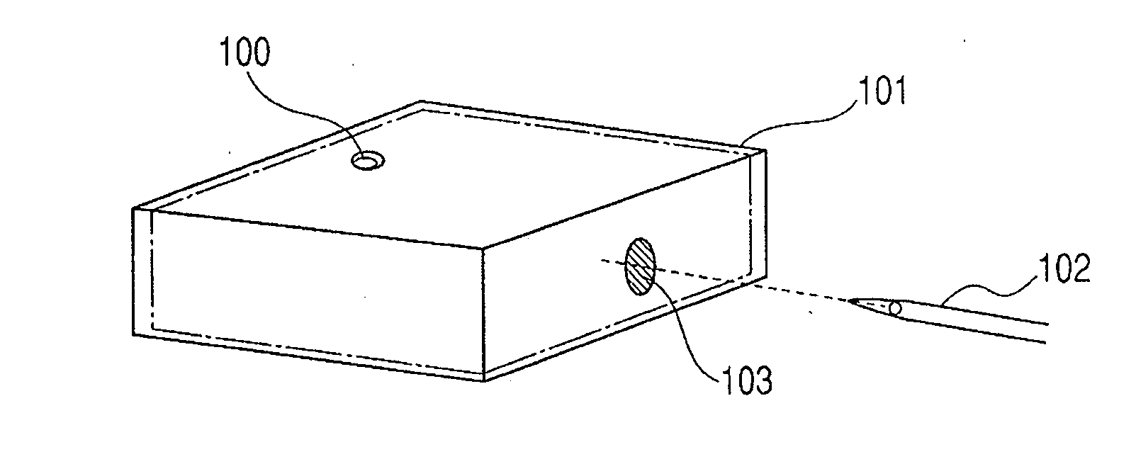
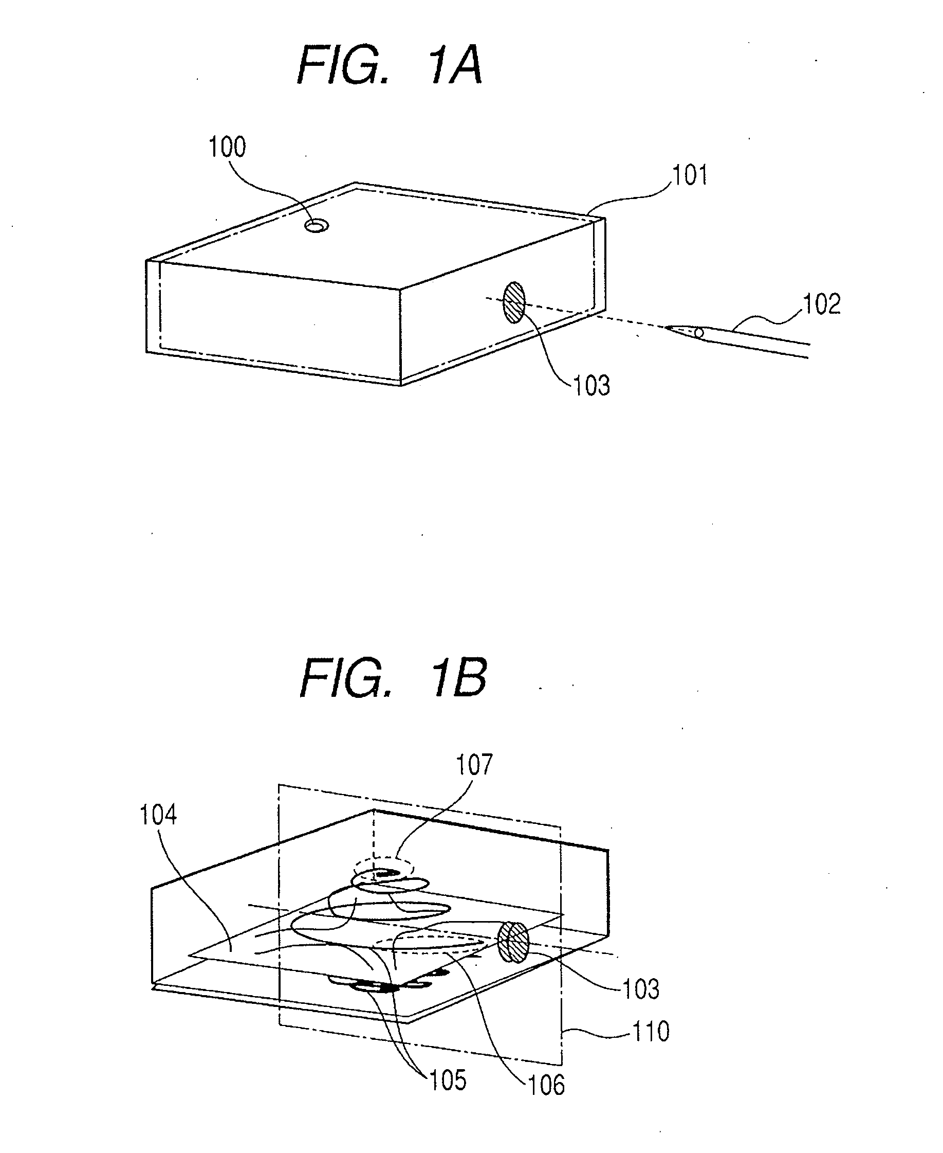
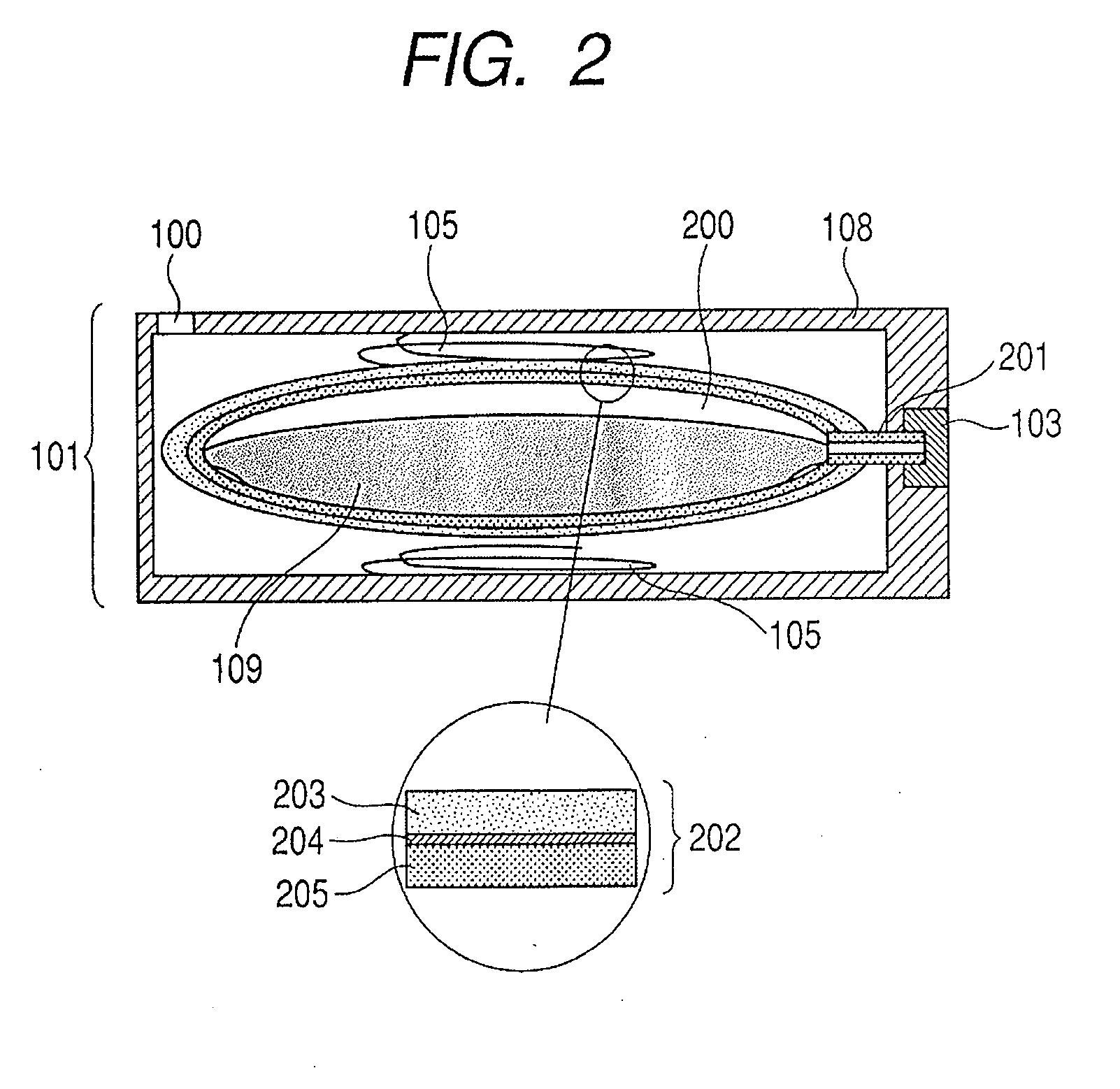
[0037]As one example of the ink tank for the ink jet recording device of the present invention, FIGS. 1A, 1B and 2 illustrate a replaceable ink cartridge. FIG. 1A is a schematic perspective view of the ink cartridge, FIG. 1B is a schematic perspective view cut along the broken line of FIG. 1A, and FIG. 2 is a schematic sectional view cut along a broken line 110 of FIG. 1B. The ink cartridge includes an ink bag 104 which is an ink storage section; an exterior material 101 in which the ink bag is stored; a rubber stopper 103 disposed at a side surface of the exterior material; and a guide tube 201 which connects the rubber stopper 103 to the ink bag 104. A hollow needle 102 is inserted into the rubber stopper 103 to form an ink channel between the ink bag and a discharge port of an ink jet recording head. Ink 109 can be derived from the ink bag to the channel, and discharged from the discharge port of the ink jet recording head. In the ink cartridge, as shown in FIG. 1B, coil springs ...

embodiment 2

[0046]As another example of the ink tank for the ink jet recording device of the present invention, FIGS. 5A, 5B and 6 illustrate a replaceable ink cartridge. FIG. 5A is a schematic perspective view of the ink cartridge, FIG. 5B is a schematic perspective view cut along the broken line of FIG. 5A, and FIG. 6 is a schematic sectional view cut along a broken line 510 of FIG. 5B. The ink cartridge includes an ink bag 511 which is an ink storage section stored in the ink cartridge; an exterior material 501 in which the ink bag is stored; a rubber stopper 503 disposed at a side surface of the exterior material; and a guide tube 506 which connects the rubber stopper 503 to the ink bag 511. A hollow needle 502 is inserted into the rubber stopper 503 to form an ink channel between the ink bag and a discharge port of an ink jet recording head. Ink 509 can be derived from the ink bag to the channel, and discharged from the discharge port of the ink jet recording head.

[0047]The ink bag 511 of ...


PUM


Abstract

There is disclosed an ink tank capable of inhibiting penetration of a gas even in an ink storage section made of a resin, having such a flexibility as to easily apply a negative pressure to ink, having an excellent resource protective property and applicable even to a small and inexpensive ink jet recording device having a large degree of freedom in design. In the ink tank for the ink jet recording device having the ink storage section made of a plastic, the ink storage section has a coating layer including a liquid retaining member capable of retaining ink on an inner surface or an outer surface thereof. The liquid retaining member can include a foam material, a fiber material or a gel-like substance. In the ink storage section, the liquid retaining member included in the coating layer including the liquid retaining member capable of retaining the ink on the outer surface thereof includes a moisture adsorbent which adsorbs a moisture.

Description

BACKGROUND OF THE INVENTION[0001]1. Field of the Invention[0002]The present invention relates to an ink tank for an ink jet recording device, which inhibits penetration of a gas and which is suitable for a small-sized flexible ink jet recording device having a high use efficiency of ink.[0003]2. Description of the Related Art[0004]An ink jet recording device includes an ink jet recording head which flies ink as liquid droplets in response to an applied electric signal, and the ink is supplied to the head from an ink reservoir referred to as an ink tank or an ink cartridge through an ink channel. During the supply of the ink, it is demanded that an appropriate negative pressure be maintained with respect to the recording head, evaporation of the ink be prevented to inhibit a change of a physical property and generation and mixture of bubbles in the ink be inhibited to smoothly distribute the ink.[0005]The inhibition of the evaporation of the ink is noted in a supply system of the ink...

Claims


Application Information

Patent Timeline
Patent Type & Authority Applications(United States)
IPC IPC(8): B41J2/175
CPCB41J2/17506B41J2/17513B41J2/17559B41J2/17556B41J2/17553
Inventor UJITA, TOSHIHIKOYAMAMOTO, HAJIME
Owner CANON KK
Why Eureka
Try Eureka