Aspherical lens and optical instrument using the same

a technology applied in the field of aspherical lenses and optical instruments, can solve the problems of narrow degree of freedom upon fabricating a large aspherical lens in particular, the restriction of designing an aspherical surface, and the high cost of fabricating, so as to achieve good optical performance, large degree of freedom in design, and compact dimension

Active Publication Date: 2008-04-29
NIKON CORP
View PDF14 Cites 13 Cited by
  • Summary
  • Abstract
  • Description
  • Claims
  • Application Information

AI Technical Summary

Benefits of technology

[0011]The present invention is made in view of the aforementioned problems and has an object to provide an aspherical lens having compactness in dimension, large degree of freedom in design, and good optical performance, with increasing in productivity, and lowering production cost.
[0013]In one preferred embodiment of the present invention, the second aspherical surface preferably has higher fabrication accuracy than that of the first aspherical surface.
[0021]A second aspect of the present invention provides an aspherical lens composed of a substrate member and a member having different composition formed on the substrate member, a boundary between the substrate member and the member having different composition being formed by a first aspherical surface, and a surface of the member having different composition opposite to the boundary being formed by a second aspherical surface having higher fabrication accuracy than that of the first aspherical surface.

Problems solved by technology

Generally, when a aspherical lens is to be fabricated by means of glass molding, since the dimension of the aspherical lens to be molded is restricted by required precision thereof, degree of freedom upon fabricating an aspherical lens in particular a large one becomes narrow.
Even if a large diameter aspherical lens can be fabricated, the fabricating cost becomes extremely high.
Moreover, an aspherical lens is fabricated by means of a fine grinding or a polishing, in addition to the high fabrication cost, it has a structural difficulty in grinding a concave surface, so that it becomes crucial restriction on designing an aspherical surface.
However, in this compound type aspherical lens, when the shape of the resin aspherical surface becomes largely different from that of the spherical glass substrate, the thickness of the resin becomes large, so that it becomes difficult to fabricate an aspherical surface with high precision.
Moreover, there is a defect that variation in the shape excessively increases upon variation in environment such as temperature and humidity.
Accordingly, it has been impossible to realize a compound type aspherical lens with a large diameter and a large resin thickness.
Accordingly, in this technology, since refractive index of the glass substrate is fixed to that of the resin, degree of freedom in design has been excessively restricted.
When a wide-angle lens or a super wide-angle lens is to be designed by using such a compound type aspherical lens as, in particular, a negative lens, since a glass material having refractive index and Abbe number corresponding to the resin material is applied, it becomes difficult to correct Petzval sum and lateral chromatic aberration.

Method used


Image

  • Aspherical lens and optical instrument using the same
  • Aspherical lens and optical instrument using the same
  • Aspherical lens and optical instrument using the same

Examples


example 1

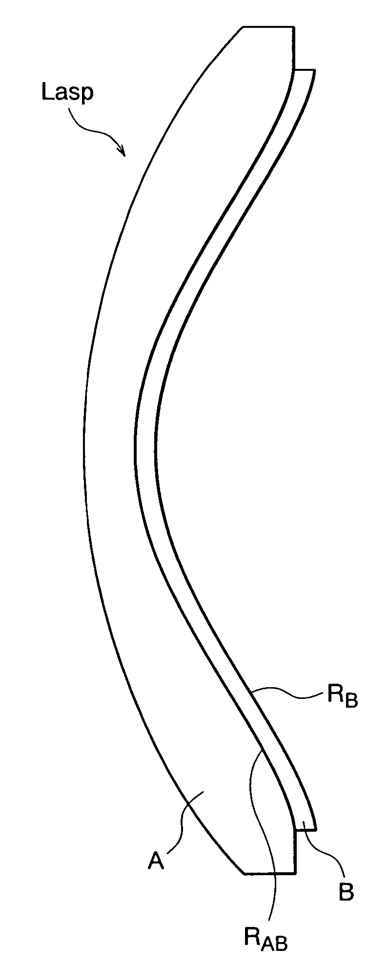
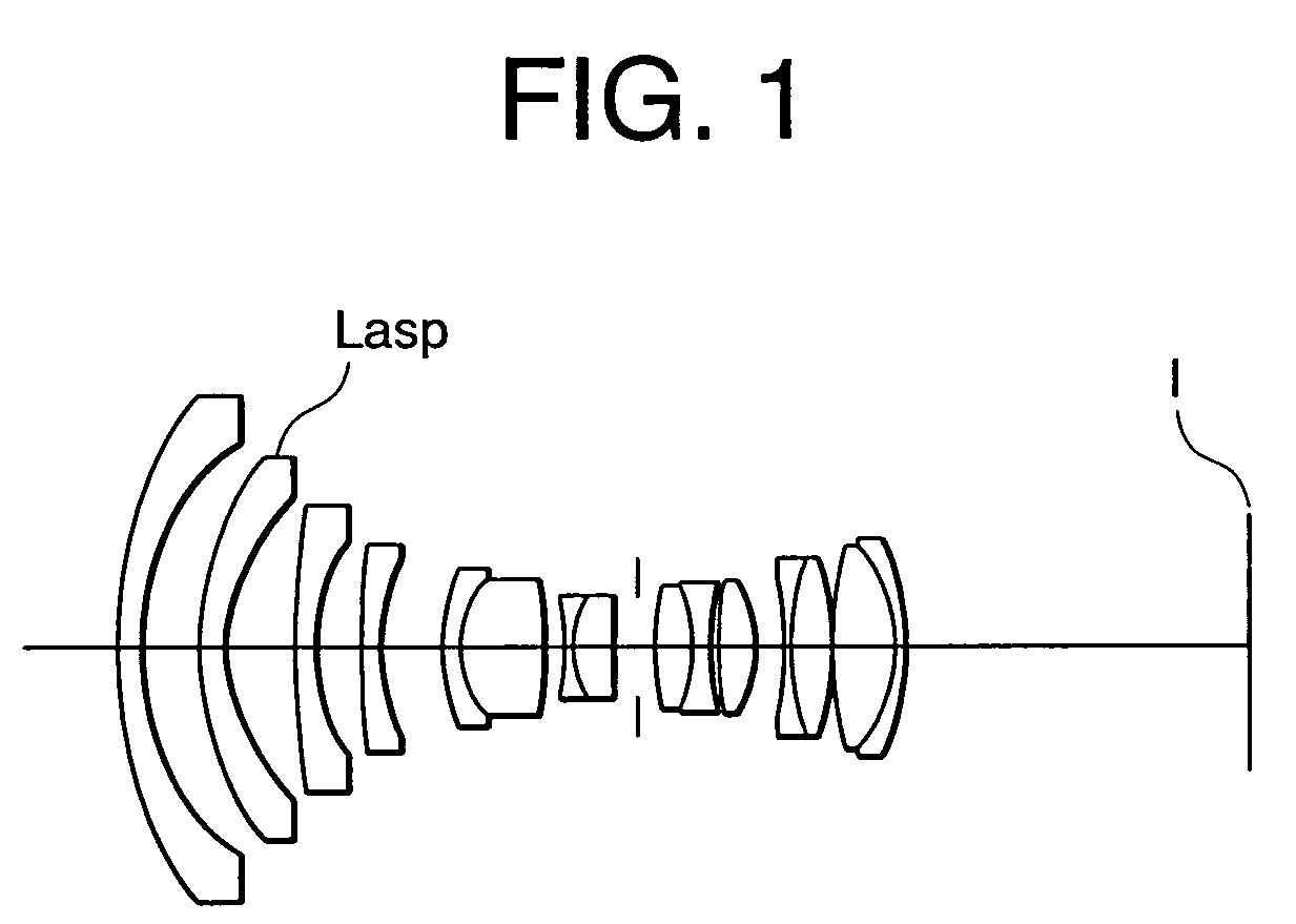
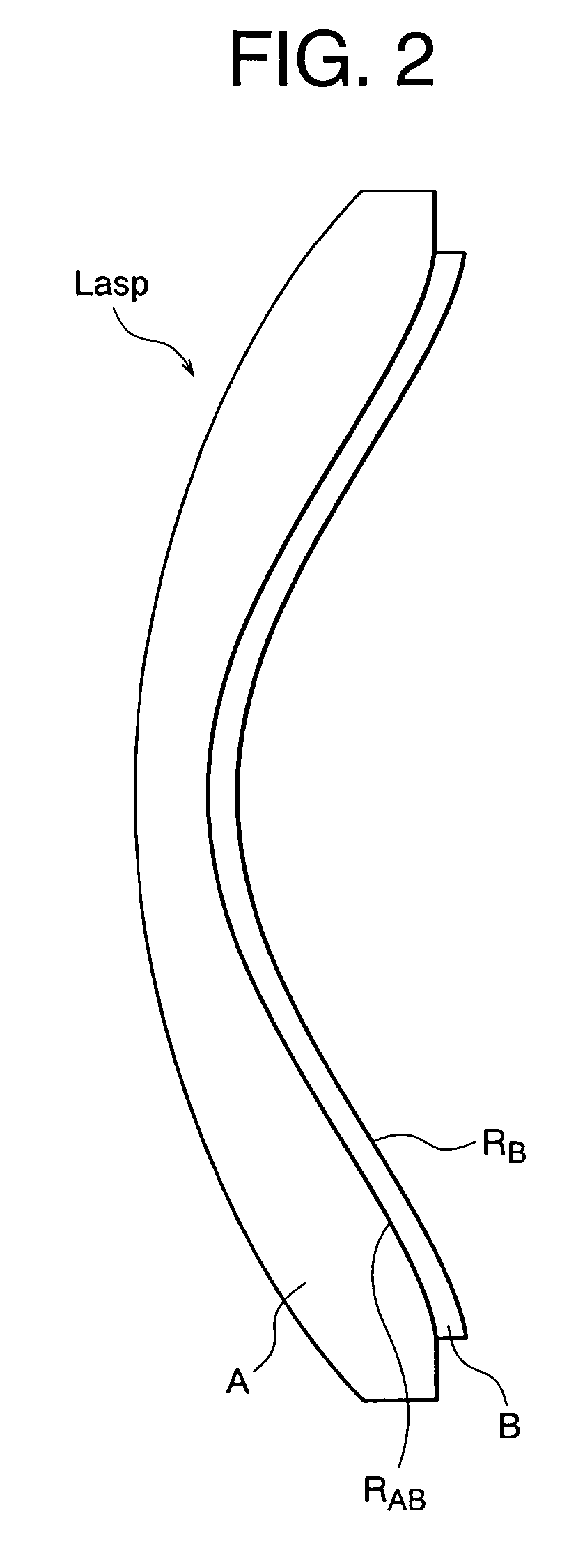
[0061]FIG. 1 is a diagram showing a lens construction of a super wide-angle lens equipped with an aspherical lens according to Example 1 of the present invention. FIG. 2 schematically shows the aspherical lens according to the present invention.

[0062]In the super wide-angle lens shown in FIG. 1, the present invention is applied to the second lens element Lasp from the object side. As shown in FIG. 2, the lens element Lasp is composed of a compound type aspherical lens constructed by a negative meniscus lens A (substrate member A) having a convex surface facing to the object and an aspherical surface RAB with low fabrication accuracy formed on a concave surface, and a resin layer B (member B) having substantially the same thickness formed on the image side of the lens A having an aspherical surface Rb with high fabrication accuracy facing to the image. Incidentally, the above-described construction of the lens Lasp is commonly used in each Example applying an aspherical lens accordin...

example 2

[0081]FIG. 4 is a diagram showing lens construction of a zoom lens system equipped with an aspherical lens according to Example 2 of the present invention together with a moving trajectory of each lens group upon zooming.

[0082]As shown in FIG. 4, the zoom lens system according to Example 2 of the present invention is a so-called negative-positive two-group zoom lens composed of, in order from an object, a negative lens group and a positive lens group. In Example 2, an aspherical surface is included in the most object side lens, the third lens from object side that is a compound type aspherical lens constructed by a glass material and a resin material, and the most image side lens that is a glass aspherical lens. In Example 2, the present invention is applied to the most object side lens Lasp.

[0083]Various values associated with a zoom lens system equipped with an aspherical lens according to Example 2 of the present invention are shown in Table 2.

[0084]

TABLE 2[Specifications]WTf =12...

example 3

[0091]FIG. 7 is a diagram showing a lens construction of a super wide-angle lens equipped with an aspherical lens according to Example 3 of the present invention.

[0092]The super wide-angle lens shown in FIG. 7 has basically the same construction as the super wide-angle lens according to Example 1 and the present invention is applied to the second lens Lasp from the object side.

[0093]Various values associated with a super wide-angle lens equipped with an aspherical lens according to Example 3 of the present invention are shown in Table 3.

[0094]

TABLE 3[Specifications]f =9.62ω =112.9°FNO =2.8[Lens Data]rdνn 1)46.02093.0042.721.83481 2)29.87426.55 3)33.49952.4749.521.74443 4*)13.77220.0353.221.69350(Lasp) 5*)13.77228.50 6)163.14572.0065.471.60300 7)23.11394.87 8*)37.11360.5038.091.55389 9)181.74131.8049.611.7725010)22.75076.9111)25.47021.8042.721.8348112)11.76159.4734.471.6398013)−33.11292.0514)−71.18911.3142.721.8348115)10.60094.7934.471.6398016)−62.12882.5017>0.00002.50Aperture Stop18...


PUM


Abstract

An object is to provide an aspherical lens having compactness in dimension, large degree of freedom in design, and good optical performance, with increasing in productivity, and lowering production cost. The aspherical lens constructed by a substrate member A and a member B having different composition formed on the substrate member A. A boundary between the substrate member A and the member B having different composition is formed by a first aspherical surface RAB, and a surface of the member B having different composition opposite to the boundary being formed by a second aspherical surface RB having higher fabrication accuracy than that of the first aspherical surface RAB, and given conditional expressions are satisfied.

Description

[0001]The disclosures of the following priority application is herein incorporated by reference:[0002]Japanese Patent Application No. 2004-289042 filed on Sep. 30, 2004.BACKGROUND OF THE INVENTION[0003]1. Field of the Invention[0004]The present invention relates to an aspherical lens and an optical instrument using the aspherical lens.[0005]2. Related Background Art[0006]Generally, when a aspherical lens is to be fabricated by means of glass molding, since the dimension of the aspherical lens to be molded is restricted by required precision thereof, degree of freedom upon fabricating an aspherical lens in particular a large one becomes narrow. Even if a large diameter aspherical lens can be fabricated, the fabricating cost becomes extremely high. Moreover, an aspherical lens is fabricated by means of a fine grinding or a polishing, in addition to the high fabrication cost, it has a structural difficulty in grinding a concave surface, so that it becomes crucial restriction on designi...

Claims


Application Information

Patent Timeline
Patent Type & Authority Patents(United States)
IPC IPC(8): G02B3/02G02B13/18
CPCG02B13/18
Inventor SATO, HARUOKIMURA, YOKO
Owner NIKON CORP
Why Eureka
Try Eureka