Coaxial Microwave Plasma Torch

a plasma torch and coaxial microwave technology, applied in the field of microwave plasma torch, can solve the problems of difficult downsizing of plasma torch, low degree of flexibility in device design, energy loss, etc., and achieve the effect of reducing the degree of freedom in design, reducing the cost of plasma generation, and significantly increasing the energy efficiency of plasma torch

Active Publication Date: 2007-09-13
THREE TEC CO LTD
View PDF6 Cites 11 Cited by
  • Summary
  • Abstract
  • Description
  • Claims
  • Application Information

AI Technical Summary

Benefits of technology

[0016] According to the present invention, since the whole of a plasma torch maintains its coaxial configuration and thus includes no oscillator, different from the conventional microwave plasma torch, a microwave to be transmitted in a coaxial cable is supplied in a coaxial mode as it is to an antenna, and plasma generates at the tip of the antenna. Therefore, energy efficiency of the plasma torch is significantly higher than in the conventional case, and further, plasma can be generated with ease even in atmospheric pressure. Moreover, according to the present invention, different from the conventional waveguide plasma torch, there is no need to use a matching device or a light reflector so that a larger degree of freedom in design can be obtained and the plasma torch can thus be downsized.

Problems solved by technology

Hence the conventional waveguide microwave plasma torch has a problem of having a low degree of flexibility in device design to limit an attempt to downsize the device.
However, according to this configuration, the use of the oscillator has required the plasma torch to be kept in a certain degree of size, making it difficult to downsize the plasma torch.
Further, according to this configuration, the microwave is once converted from a coaxial mode into another mode and then again converted into the coaxial mode during transmission of the microwave from the coaxial line into the oscillator, but there has been a problem that, when such mode conversion is performed, energy loss occurs in response to the conversion, thereby decreasing an energy efficiency.
In addition, according to this configuration, it has been difficult to ignite plasma in atmospheric pressure.

Method used


Image

  • Coaxial Microwave Plasma Torch
  • Coaxial Microwave Plasma Torch
  • Coaxial Microwave Plasma Torch

Examples


Embodiment Construction

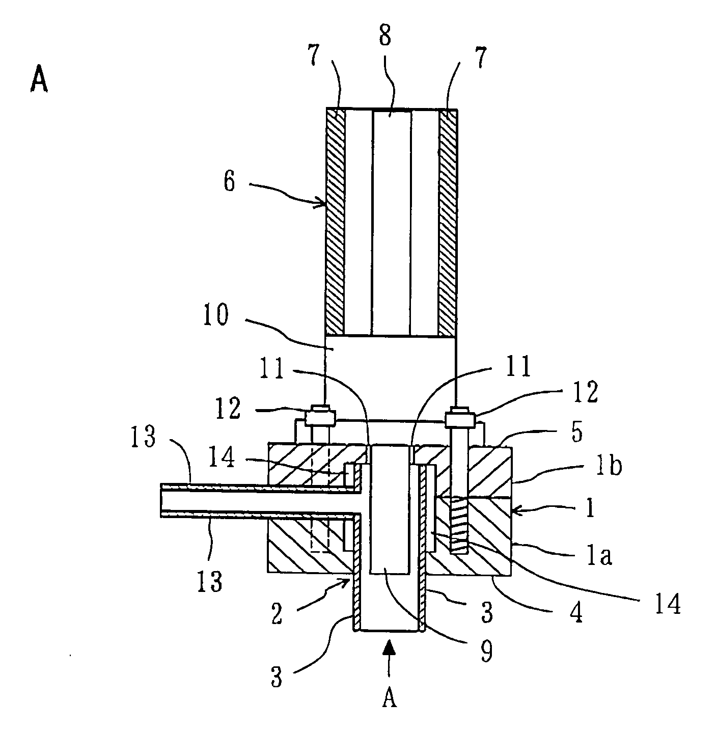
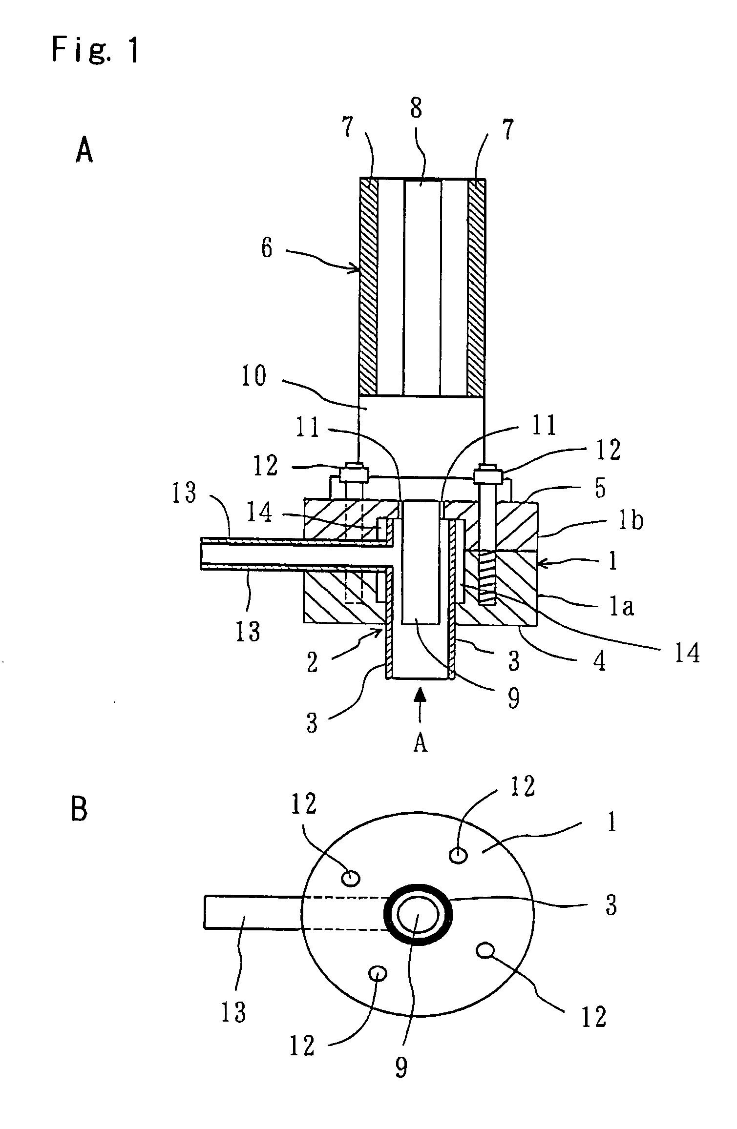
[0035] In the following, a preferred example of the present invention is described with reference to attached drawings. FIG. 1 shows a coaxial microwave plasma torch according to one example of the present invention: (A) is a sectional side view, and (B) is a plan view as seen from a direction indicated by arrow A. With reference to FIG. 1, the coaxial microwave plasma torch of the present invention includes: an outside conductor 1 formed in a cylindrical shape; a cylindrical electric discharge tube 3, fixedly inserted into an axial hole 2 formed in the outside conductor 1 on one end face side 4; and a coaxial cable 6 for microwave transmission, having one end fitted to the other end face 5 of the outside conductor 1 from outside.

[0036] In this example, the outside conductor 1 is constituted by a bonded article of a cylindrical first portion 1a on the one end face 4 side and a cylindrical second portion 1b on an other end face 5 side. Further, the axial hole 2 extends along a centr...


PUM

PropertyMeasurementUnit
lengthaaaaaaaaaa
phaseaaaaaaaaaa
electrical insulating propertyaaaaaaaaaa

Abstract

A coaxial microwave plasma torch, comprising, an outside conductor (1) formed in a cylindrical shape, a cylindrical electric discharge tube (3) fixedly inserted into an axial hole (2) formed in the outside conductor on one end face (4) side, and a coaxial cable (6) having one end fitted to the other end face of the outside conductor. An antenna (9) electrically connected to an inside conductor (8) is fitted to the one end of the coaxial cable and extended into the electric discharge tube through a through-hole (11) axially passed through between the other end face (5) of the outside conductor and the bottom ice of the axial hole. The outside conductor (7) of the coaxial cable is electrically connected to the outside conductor, and a gas inlet pipeline (13) supplying a gas into the electric discharge tube is fitted in the outside conductor.

Description

TECHNICAL FIELD [0001] The present invention relates to a microwave plasma torch, and particularly to a coaxial microwave plasma torch BACKGROUND ART [0002] As a microwave plasma torch capable of generating plasma in atmospheric pressure, there is conventionally known a waveguide microwave plasma torch (see Patent Document No. 1). This conventional waveguide microwave plasma torch roughly includes three components: a stub tuner, a waveguide and a reflecting plate, and the torch further requires an ignition device for generating plasma in atmospheric pressure and thus has a large number of components. Hence the conventional waveguide microwave plasma torch has a problem of having a low degree of flexibility in device design to limit an attempt to downsize the device. [0003] As a plasma torch to solve this drawback of the conventional waveguide plasma torch, there is proposed a coaxial microwave plasma torch having a configuration inherited from a configuration of a helical resonator ...

Claims


Application Information

Patent Timeline
Patent Type & Authority Applications(United States)
IPC IPC(8): H05H1/30H05H1/24
CPCH05H1/30H05H1/46H05H1/463H05H1/4637H05H1/4622
Inventor FUJII, SHUITSURAMASAMY, RAJUURAYAMA, TAKUYAFUJIOKA, KAZUNARI
Owner THREE TEC CO LTD
Why Eureka
Try Eureka