
Sink mounting assembly, sink lighting assembly, and methods of installation

Inactive Publication Date: 2022-10-27
HOCAOGLU MEHMET
View PDF0 Cites 0 Cited by
  • Summary
  • Abstract
  • Description
  • Claims
  • Application Information

AI Technical Summary

Benefits of technology

The invention is a sink mounting assembly and lighting system that overcomes the limitations of traditional sink configurations. It includes a unique junction for mounting the sink and a light element that improves its appearance. Additionally, it allows for the sink to be installed in multiple positions on the counter. The technical effects include improved aesthetic appeal and versatility in installation options.

Problems solved by technology

But kitchen sinks are rarely complimented for their aesthetic beauty.
This is unfortunate, particularly because guests seem to always find their way into the kitchen and it is the kitchen that is often the gathering spot during parties.
It is also unfortunate that sinks are not more attractive because modern homes are featuring open kitchen designs, where the sink is not only visible from the kitchen, it is often visible from the front room, dining room, outdoor area, and other places within the home.
However, debris can sometimes get caught at the edge where the sink and countertop meet.
One such structure is shown in FIG. 37. FIG. 37 also shows how the lip is always visible top of the countertop and is not attractive.
First, the undermount sink is lowered by the thickness of the LED element, which can create issues with the bottom of the sink making contact with valves and pipes under the sink and it reduces valuable storage space under the sink.
Second, this configuration introduces multiple seams—one between the sink lip and the bottom of the LED structure and another between the LED structure and the bottom surface of the countertop.
Each of these seems is a potential portal for water to pass through and fall to the area under the sink, which can eventually rot the cabinet material and / or form mold.
Currently, there is no known sink that allows for versatile installation and provides decorative lighting features.

Method used


Image

  • Sink mounting assembly, sink lighting assembly, and methods of installation
  • Sink mounting assembly, sink lighting assembly, and methods of installation
  • Sink mounting assembly, sink lighting assembly, and methods of installation

Examples


Embodiment Construction

[0076]While the specification concludes with claims defining the features of the invention that are regarded as novel, it is believed that the invention will be better understood from a consideration of the following description in conjunction with the drawing figures, in which like reference numerals are carried forward. It is to be understood that the disclosed embodiments are merely exemplary of the invention, which can be embodied in various forms.

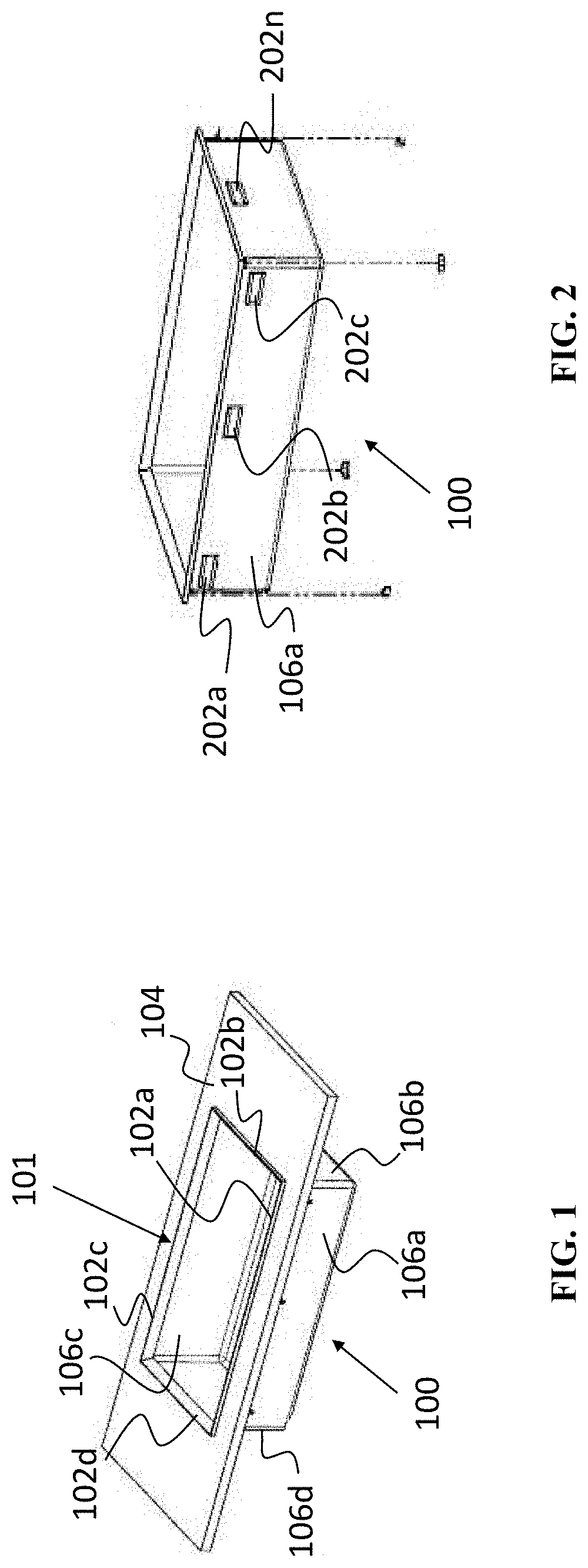
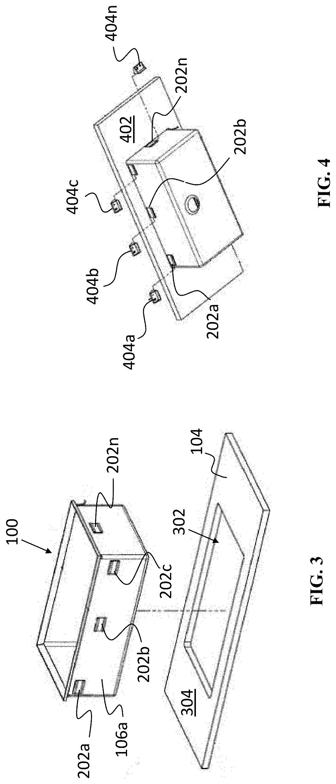
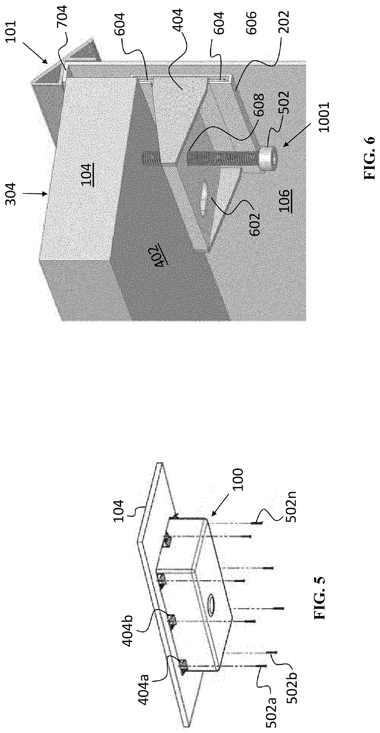
[0077]The present invention provides novel and efficient sink installation and lighting hardware assemblies and methods of installation, the assemblies and methods being configured to light a sink interior while simultaneously ensuring secure installation of the sink in multiple positions relative to a countertop. The lighting assembly advantageously prevents debris and other applicable undesirable particles from getting caught in corners and edges where the sink meets with one or more planar surfaces of the countertop in which the sin...


PUM


Abstract

A lighted sink includes a sink with a sink lighting assembly coupled to an upper end of the sink. The lighting assembly projects light downward and into the sink, which at the same time, protects the light emitting element from moisture and contaminants through a combination of protective walls that physically house the light emitting element and leave at least one side open to a transparent window that allows light to broadcast to and illuminate an interior of the sink.

Description

FIELD OF THE INVENTION[0001]The present invention relates generally to sinks, and, more particularly, relates to mounting sinks with decorative lighting elements on, in, and under a countertop.BACKGROUND OF THE INVENTION[0002]Every modern house has a kitchen and every kitchen has sink. Because the kitchen sink is used considerably more than any other part of the kitchen, it is usual located in the center and is a focal point. But kitchen sinks are rarely complimented for their aesthetic beauty. While some high-end countertops and sinks are certainly not unattractive, the sink is not usually the subject of compliments from guests in the home. This is unfortunate, particularly because guests seem to always find their way into the kitchen and it is the kitchen that is often the gathering spot during parties. It is also unfortunate that sinks are not more attractive because modern homes are featuring open kitchen designs, where the sink is not only visible from the kitchen, it is often ...

Claims


Application Information

Patent Timeline
IPC IPC(8): E03C1/33E03C1/182F21V33/00
CPCE03C1/33E03C1/182F21V33/004F21Y2115/10F21S4/28F21Y2103/20F21W2121/00E03C1/335
Inventor HOCAOGLU, MEHMET
Owner HOCAOGLU MEHMET
Learn More