Supercharge Your Innovation With Domain-Expert AI Agents!

Device for discharging a substance

Pending Publication Date: 2022-11-10
RPC BRAMLAGE
View PDF3 Cites 0 Cited by
  • Summary
  • Abstract
  • Description
  • Claims
  • Application Information

AI Technical Summary

Benefits of technology

This patent describes a mechanism that helps a rotary handle or spindle maintain a stable position in relation to a device housing. This is accomplished through a locking mechanism that allows the handle to be locked in a variety of positions. This is particularly useful for devices with a noncircular layout design. The locked position of the handle allows for identical rotational angles and large linear displacement paths of the device's support carrying the substance.

Problems solved by technology

This does not directly result in a necessary, reliable seal.

Method used


Image

  • Device for discharging a substance
  • Device for discharging a substance
  • Device for discharging a substance

Examples


first embodiment

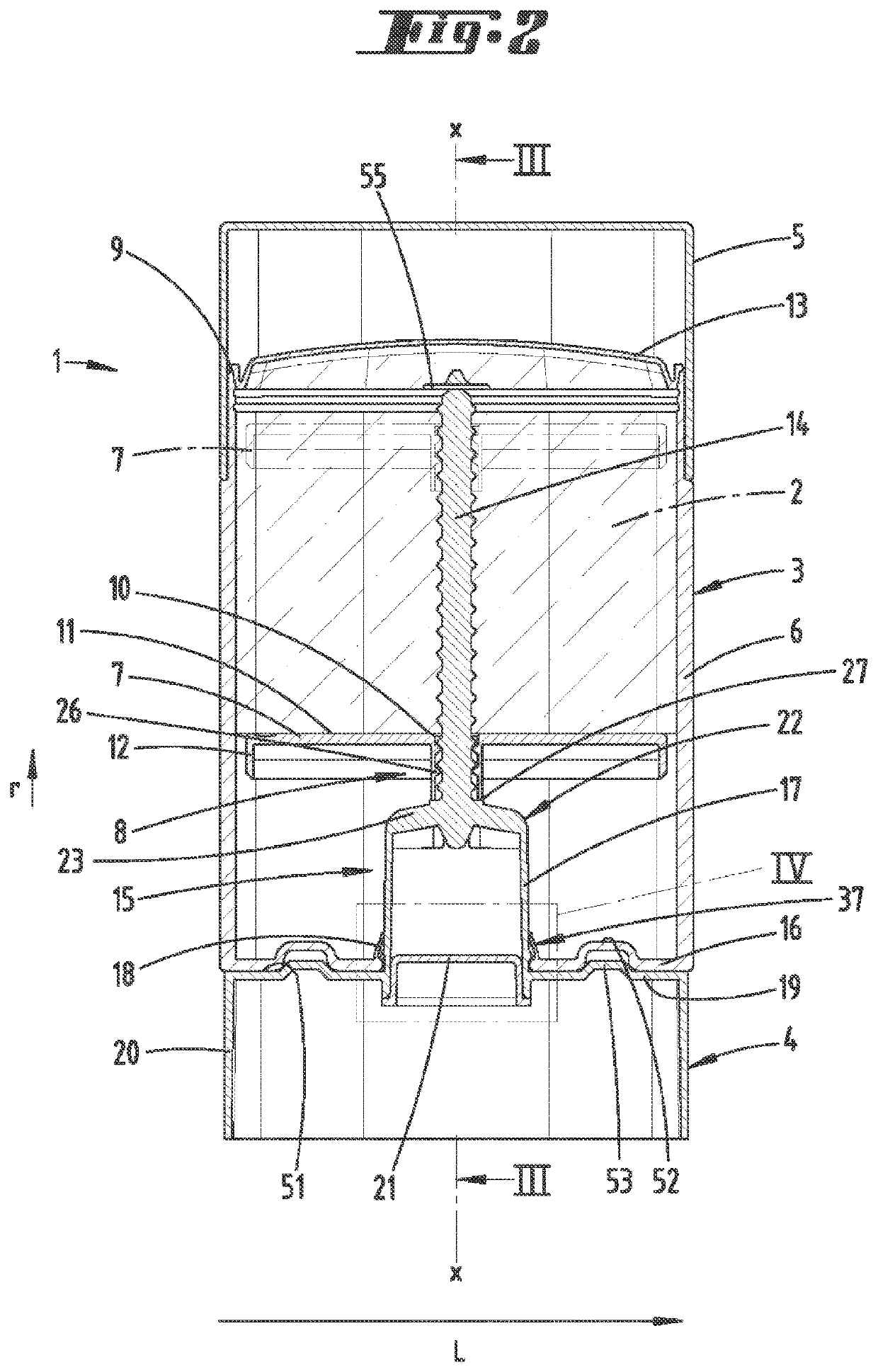
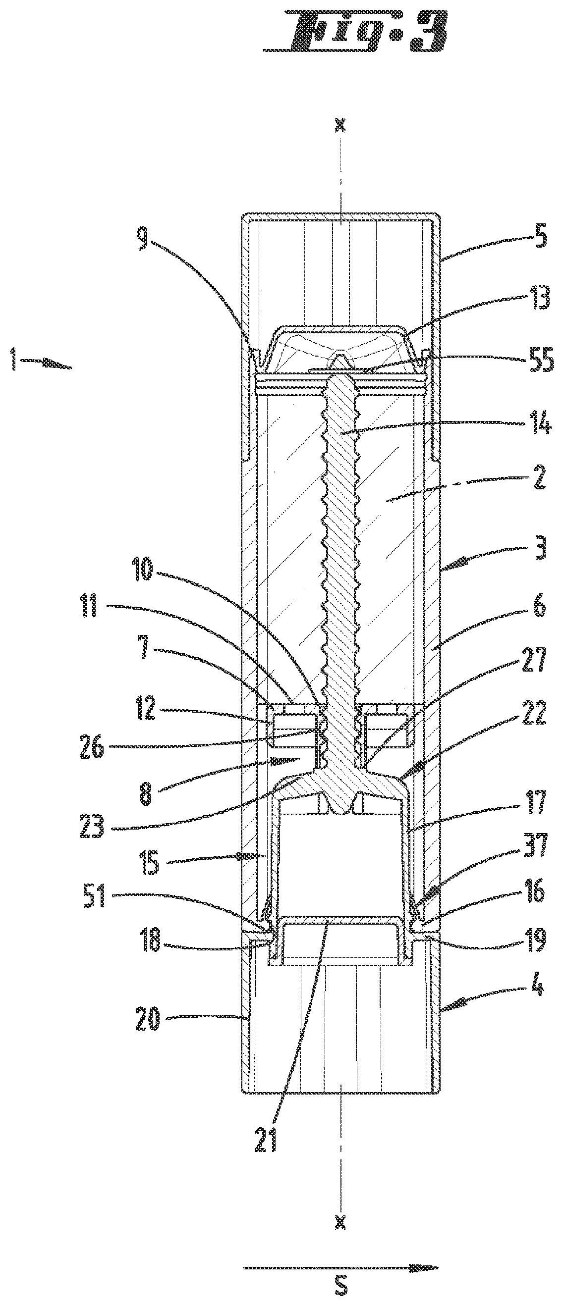
[0062]The support 7 can be moved by way of a movement unit 8 along a longitudinal axis x, which preferably forms a central longitudinal body axis of the device 1 at the same time, between a lowermost starting position, for example as shown on FIGS. 2 and 3, but beyond that, for example, also on FIGS. 8 and 9 as well as 12 and 13, and an upper extended position. In the illustration according to FIG. 2 (first embodiment of device 1), this extended position is denoted by dot-dashed lines.

[0063]The upper extended position can involve a maximum upper extended position. The support 7 can here come to abut against a stop 55 preferably designed as a radially protruding circular disk, allocated to an upper end of the spindle 14.

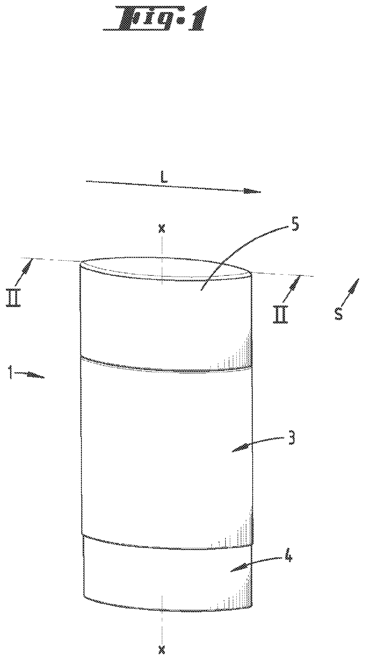
[0064]As a whole, the device housing 3 essentially determines the shape of the device 1, wherein, with reference to a layout in which the longitudinal axis x appears as a point in said layout, the device 1 and in particular the device housing 3 can have an oval outer ...

second embodiment

[0077]In the second embodiment shown on FIGS. 8 to 11, the spindle 14 and the rotary handle 4 have a two-part design. During the assembly of the device 1, these parts are connected with each other in a torsionally rigid manner, in particular by inserting the spindle 12 from above along the longitudinal axis x into a plug-in receptacle 24 of the rotary handle 4 formed concentrically to the longitudinal axis x. The plug-in receptacle 24 is here preferably surrounded at a distance by the sleeve 17.

[0078]The related end area 25 of the spindle 13 is preferably given an unround shape by flat sections in a cross section transverse to the longitudinal axis x (see also FIGS. 16 and 17), so that a torsionally rigid connection can be achieved between the spindle 14 and rotary handle 4 given a corresponding inner geometry of the plug-in receptacle 24.

[0079]Independently of the configuration of the spindle part described above, the male thread of the spindle 14 interacts with a female thread of ...

third embodiment

[0098]In the third embodiment shown on FIGS. 12 to 17, the handle cover 19 is centrally lowered like a pot. This yields a circumferential, vertically downwardly directed pot wall 45, which passes over into a pot base 46 directed transverse to the longitudinal axis x. In this embodiment, the plug-in receptacle 24 is formed on the pot base 46 facing into the interior of the sleeve section 41.

[0099]The wall of the sleeve section 41 is here formed axially downward further beyond the housing base 16, and here extends inside of the pot-shaped formation of the handle cover 19, essentially radially inwardly flanking the pot wall 45.

[0100]The end of the sleeve section 41 that faces downward in the cross section according to the illustration on FIG. 15 forms the seal protrusion 37, wherein the downwardly free seal edge 47 of the seal protrusion 37 that here results is in this cross section preferably tightly surrounded by the spindle part 16 in a U-shaped manner, here in particular the pot-sh...


PUM


Abstract

A device for discharging a substance has a device housing equipped with a movable support in order to act on the substance, and a rotary handle for moving the support between a lower starting position and an upper extended position of the support. The rotary handle forms a spindle part together with a spindle. The spindle part passes through a housing base, and is locked to the housing base and is sealed. A locking protrusion engages into a locking recess of the spindle part, and a seal protrusion sealingly rests against a circumferential surface of the spindle part. The locking recess of the spindle part is formed axially below the circumferential surface which interacts with the seal protrusion. The seal protrusion is formed on a sleeve section of the device housing, and a sleeve section seal edge is sealingly surrounded by the spindle part in a U-shaped manner.

Description

CROSS REFERENCE TO RELATED APPLICATIONS[0001]This application is the National Stage of PCT / EP2020 / 068031 filed on Jun. 26, 2020, which claims priority under 35 U.S.C. § 119 of British Application No. 1909373.1 filed on Jun. 28, 2019 and British Application No. 1916448.2 filed on Nov. 12, 2019, the disclosures of which are incorporated by reference. The international application under PCT article 21(2) was not published in English.AREA OF TECHNOLOGY[0002]The invention initially relates to a device for discharging a substance, wherein a movable support is arranged in a device housing to act on the substance, wherein a rotary handle is further designed to move the support between a lower starting position and an upper extended position of the support, and forms a spindle part with a spindle that can be rotated around a longitudinal axis provided in the movement direction of the support, wherein the spindle part passes through a housing base, and is locked and sealed to the housing base...

Claims


Application Information

Patent Timeline
IPC IPC(8): A45D40/04
CPCA45D40/04A45D40/02B65D83/0011
Inventor NIEMEYER, JESSICAHAMMERSEN, LEA
Owner RPC BRAMLAGE
Features
  • R&D
  • Intellectual Property
  • Life Sciences
  • Materials
  • Tech Scout
  • Unparalleled Data Quality
  • Higher Quality Content
  • 60% Fewer Hallucinations
Learn More