Stick slip detection system and method

Pending Publication Date: 2022-11-10
YAMATAKE HONEYWELL CO LTD
View PDF0 Cites 0 Cited by
  • Summary
  • Abstract
  • Description
  • Claims
  • Application Information

AI Technical Summary

Problems solved by technology

However, in the method disclosed in PTL 1, even if no abnormality occurs in the valve, a behavior of the measured value of a valve shaft displacement may be similar to that of a stick slip state when a control command value itself of the valve shaft displacement greatly changes, and it may be erroneously determi

Method used


Image

  • Stick slip detection system and method
  • Stick slip detection system and method
  • Stick slip detection system and method

Examples


Embodiment Construction

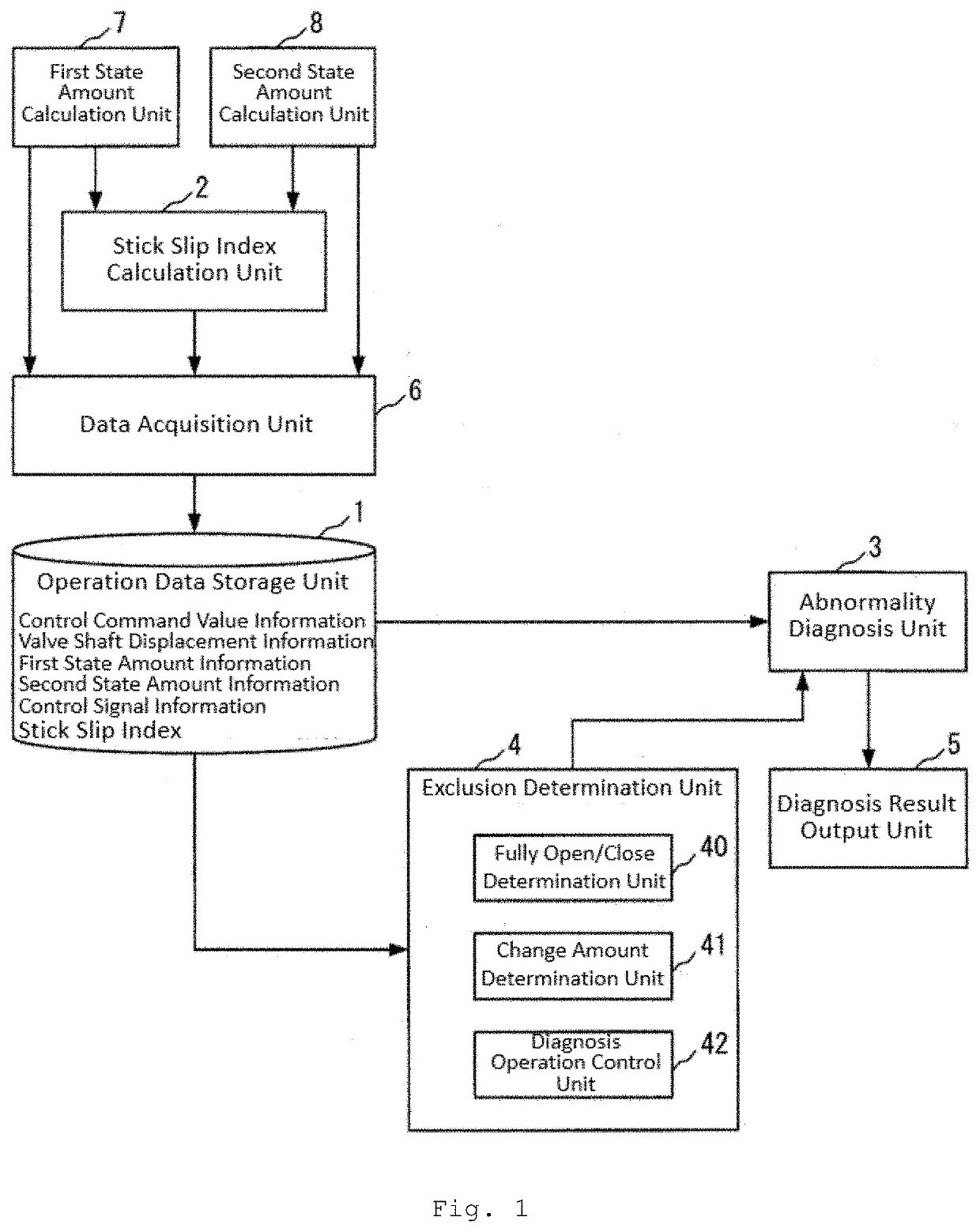
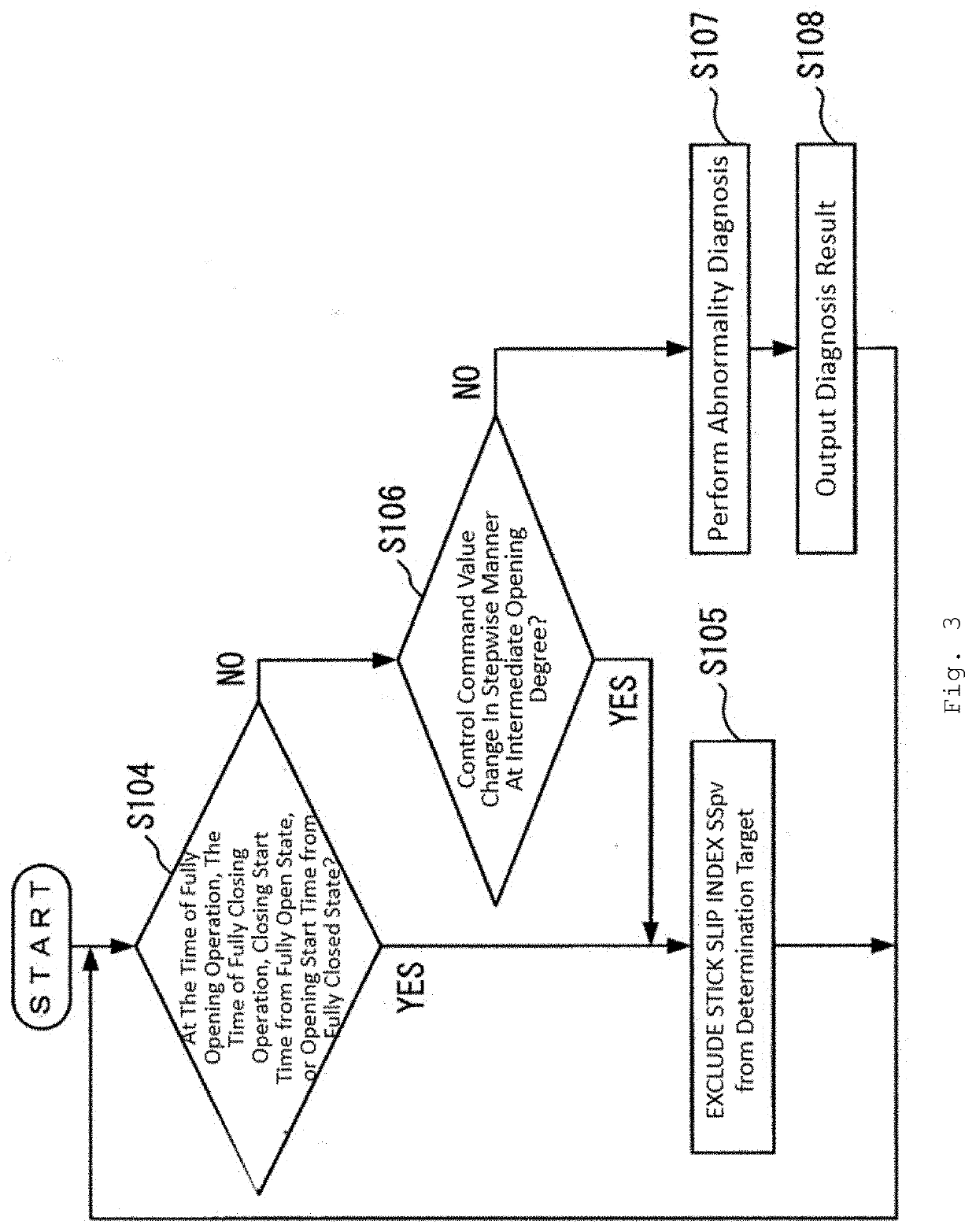
[0039]When it is determined whether a stick slip phenomenon has occurred in a valve, a veteran maintenance person knows that an erroneous determination is often made in a case where the control command value itself greatly changes. Then, it can be confirmed from a measured value that the control command value is largely changed. The present disclosure presents a method of determining whether a stick slip phenomenon has occurred after excluding data that causes erroneous determination of the stick slip phenomenon based on information on a change amount of a control command value based on knowledge of the maintenance person.

[0040]Examples of the data with a large change amount of the control command value that may cause the erroneous determination of the stick slip phenomenon include data at the time of a fully opening operation in which the valve is operated to a fully open position, data at the time of a fully closing operation in which the valve is operated to a fully closed positi...


PUM


Abstract

A stick slip detection system includes: an operation data storage unit configured to store a stick slip index, the stick slip index being a ratio of a first state amount based on a displacement of a valve shaft of a valve to be diagnosed to a second state amount based on the displacement; an abnormality diagnosis unit configured to determine whether a stick slip phenomenon occurs in the diagnosis target based on the stick slip index; and a diagnosis operation control unit configured to, when a stepwise change in a control command value in an intermediate opening degree of the valve to be diagnosed is detected, stop a determination operation of the abnormality diagnosis unit. The present disclosure makes it possible to easily reflect knowledge of an expert with respect to a diagnosis target such as a valve in the stick slip detection system and method.

Description

CROSS REFERENCE TO RELATED APPLICATIONS[0001]This patent application claims the benefit of foreign priority to Japanese Patent Application No. JP 2021-079520 filed on May 10, 2021, the disclosure of which is hereby incorporated by reference in its entirety.BACKGROUND OF THE INVENTION[0002]The present disclosure relates to a stick slip detection system and method for detecting a stick slip of a diagnosis target such as a valve, and more particularly to a technique for suppressing erroneous detection of the stick slip.[0003]A stick slip of a valve is a phenomenon in which a stop (stick) and a slide (slip) of a valve shaft are repeated. As a method of detecting a stick slip, there is a method disclosed in PTL 1. In the method disclosed in PTL 1, an average value X of absolute values of a valve shaft speed and a square root Y of a mean square of the valve shaft speed are calculated from a displacement xi of the valve shaft as shown in Equations (1) and (2) (N is the number of pieces of ...

Claims


Application Information

Patent Timeline
IPC IPC(8): F16K37/00F15B19/00
CPCF16K37/0083F15B19/005F15B2211/87G01M13/003G01N19/02G05B19/44G05B23/0235
Inventor HIRAO, KOICHIROYAMASAKI, FUMIAKI
Owner YAMATAKE HONEYWELL CO LTD
Why Eureka
Try Eureka