Circular polarizing plate
- Summary
- Abstract
- Description
- Claims
- Application Information
AI Technical Summary
Benefits of technology
Problems solved by technology
Method used
Image
Examples
Example
EVALUATION EXAMPLE 1
Evaluation of Surface Reflection Characteristics in Antireflection Films
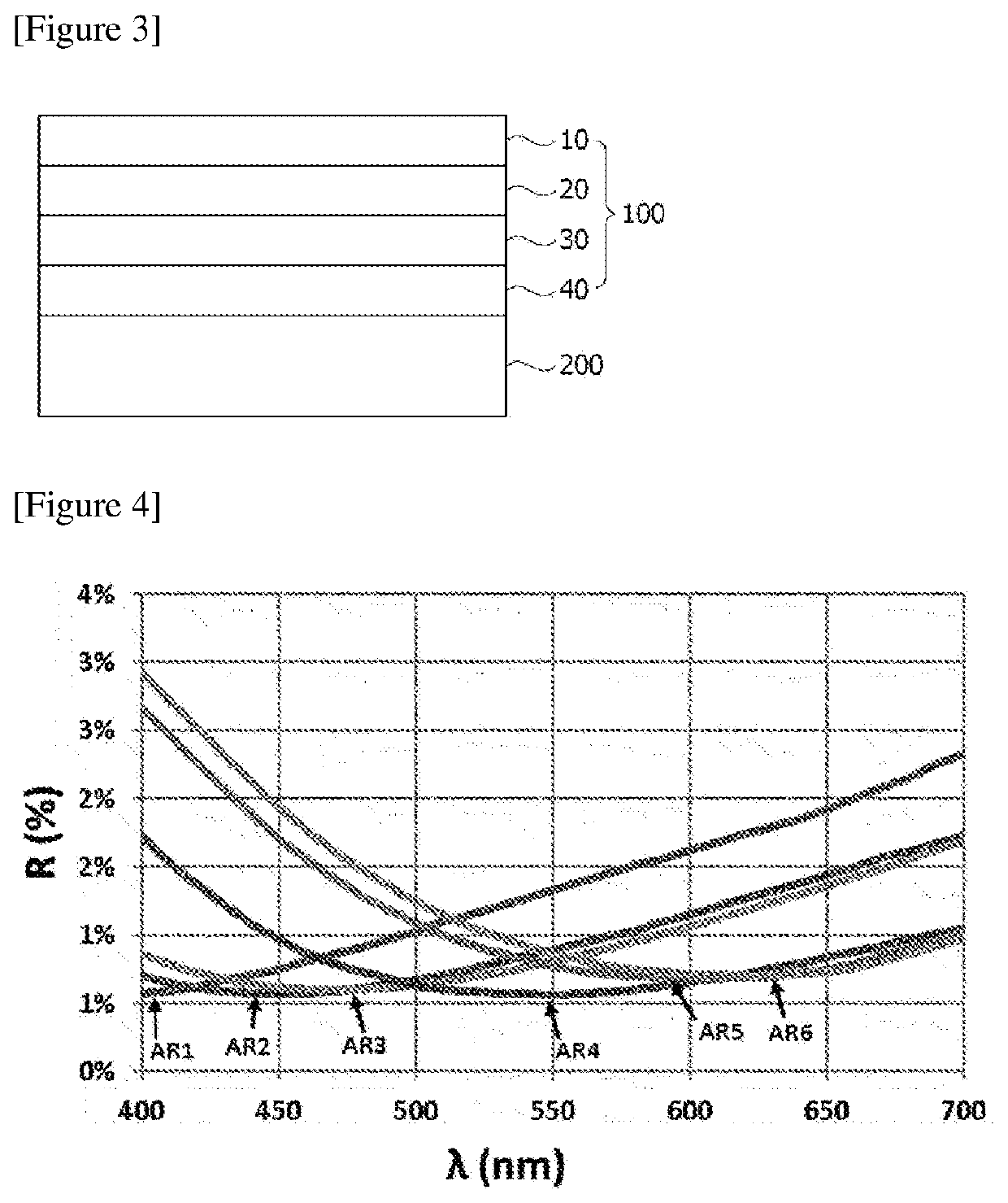
[0105]For antireflection films, reflection colors and reflectance were measured to evaluate surface reflection characteristics. Table 1 shows results of measuring lowest reflection wavelengths, reflection colors (L*a*b* color coordinates) and reflectance in the antireflection films.
[0106]The reflectance of the antireflection film was measured by attaching a black tape absorbing light to the backside of the antireflective coating layer of the base material and then using Minolta's CM-2600d equipment to measure mirror reflectance of the surface layer of the antireflective coating layer. Specifically, the reflectance is a result value of subtracting the SCE (Specular component excluded) value from the SCI (Specular component included) value among the measured values of the equipment. Simultaneously with the above measurements, CIE 1976 L*a*b* under a D65 light source condition can be obtained fr...
Example
EVALUATION EXAMPLE 2
Evaluation of Transmittance of Pressure-Sensitive Adhesive and Polarizing Plate
[0108]The transmittance of the pressure-sensitive adhesive comprising the blue cut dye and the transmittance of the polarizer before and after the attachment of the pressure-sensitive adhesive were measured, and the results are shown in FIGS. 5 and 6, respectively. The pressure-sensitive adhesive with a blue cut dye concentration of 0.3% has transmittance of 90% for a wavelength of 430 nm, the pressure-sensitive adhesive with a blue cut dye concentration of 0.6% has transmittance of 80% for a wavelength of 430 nm, and the pressure-sensitive adhesive with a blue cut dye concentration of 0.9% has transmittance of 70% for a wavelength of 430 nm.
[0109]The transmittance of the pressure-sensitive adhesive comprising the blue cut dye was measured using Shimadzu UV-3600. Specifically, it was measured using a sample that the pressure-sensitive adhesive comprising the blue cut dye was attached t...
Example
EVALUATION EXAMPLE 3
Evaluation of Reflection Characteristics of Circularly Polarizing Plate
[0111]A reflective ND (neutral density) filter with an OD (optical density) of 0.5 coated with Inconel (metal) on one side of a glass substrate purchased from Edmund Optics was used as a reflective plate to measure the reflective characteristics of the circularly polarizing plate. FIG. 7 shows the reflectance spectrum of the reflective plate. The reflectance was measured using Minolta's CM-2600d, and the reflectance was measured on the glass surface with the deposition surface of the reflective plate facing the light trap. The reflectance was obtained from the SCI (specular component included) mode value. The circularly polarizing plate was attached to the glass surface of the reflective plate, and then the reflectance and the reflection colors were measured in the same method as above. The reflectance and reflection colors are measured in the CIE 1964 / 10° standard under the D65 light source c...
PUM
 Abstract
Description
Claims
Application Information
 - R&D Engineer
- R&D Manager
- IP Professional
- Industry Leading Data Capabilities
- Powerful AI technology
- Patent DNA Extraction
Browse by: Latest US Patents, China's latest patents, Technical Efficacy Thesaurus, Application Domain, Technology Topic, Popular Technical Reports.
© 2024 PatSnap. All rights reserved.Legal|Privacy policy|Modern Slavery Act Transparency Statement|Sitemap|About US| Contact US: help@patsnap.com


