Antenna system with short cable
- Summary
- Abstract
- Description
- Claims
- Application Information
AI Technical Summary
Benefits of technology
Problems solved by technology
Method used
Image
Examples
first illustrated embodiment
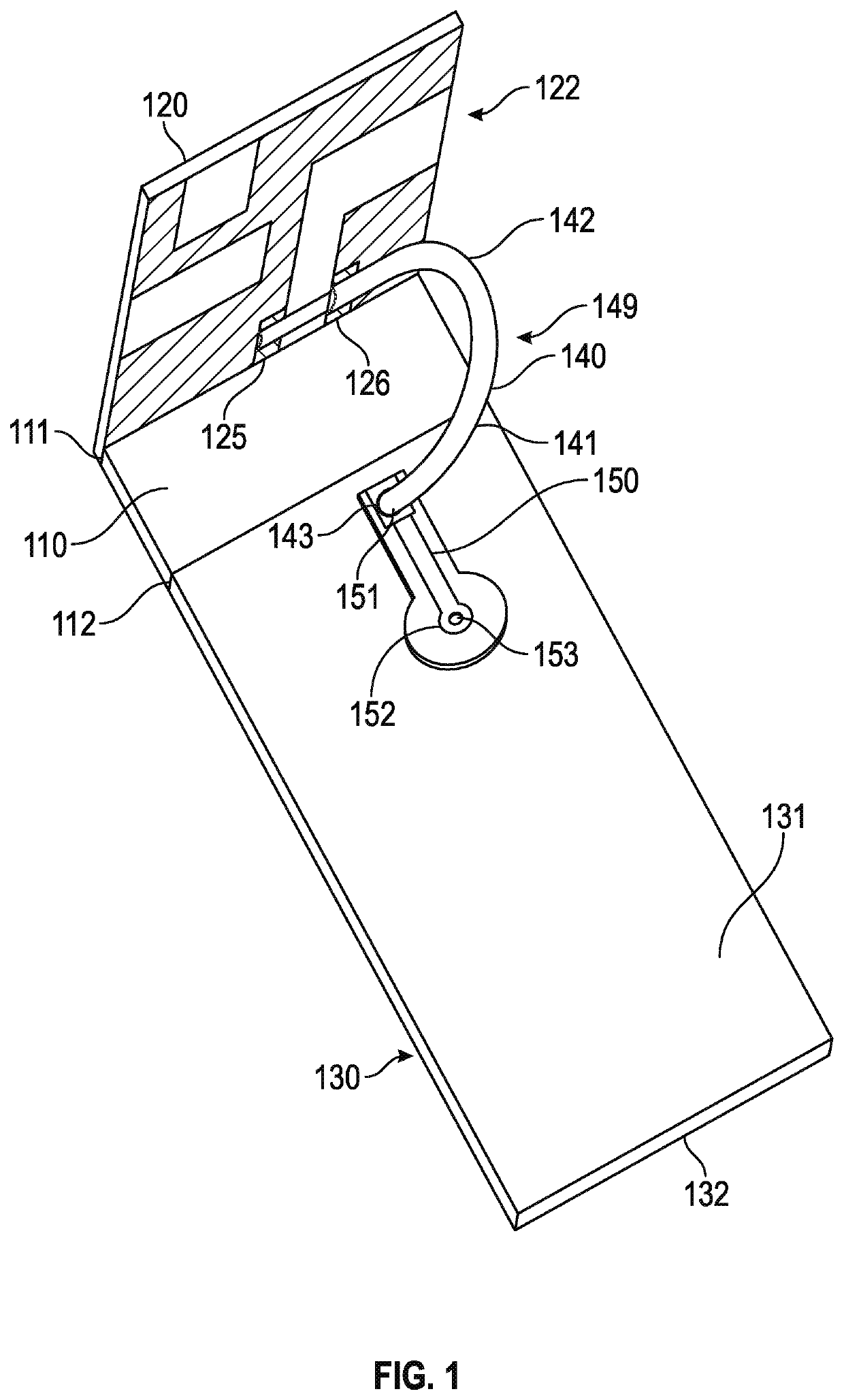
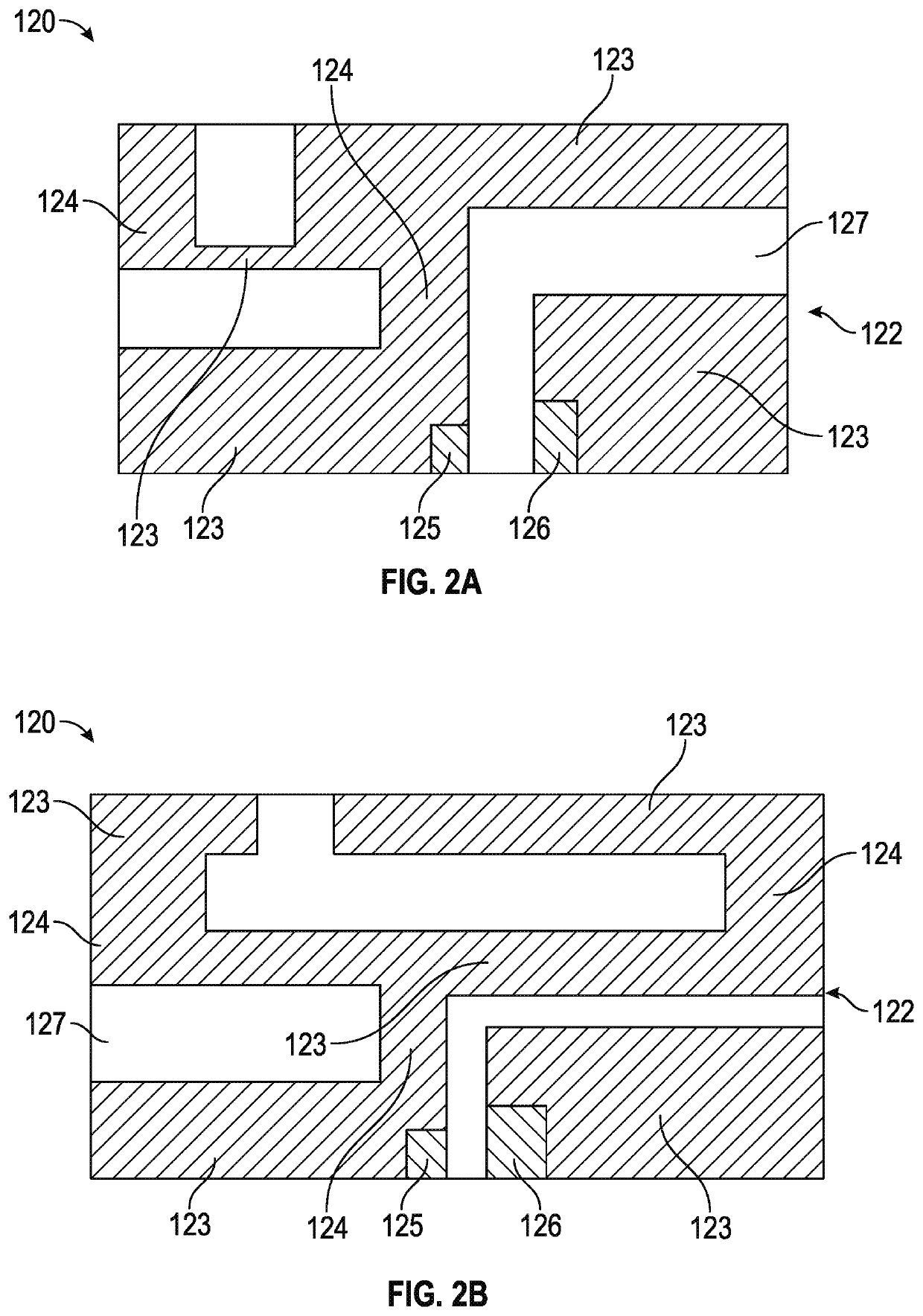
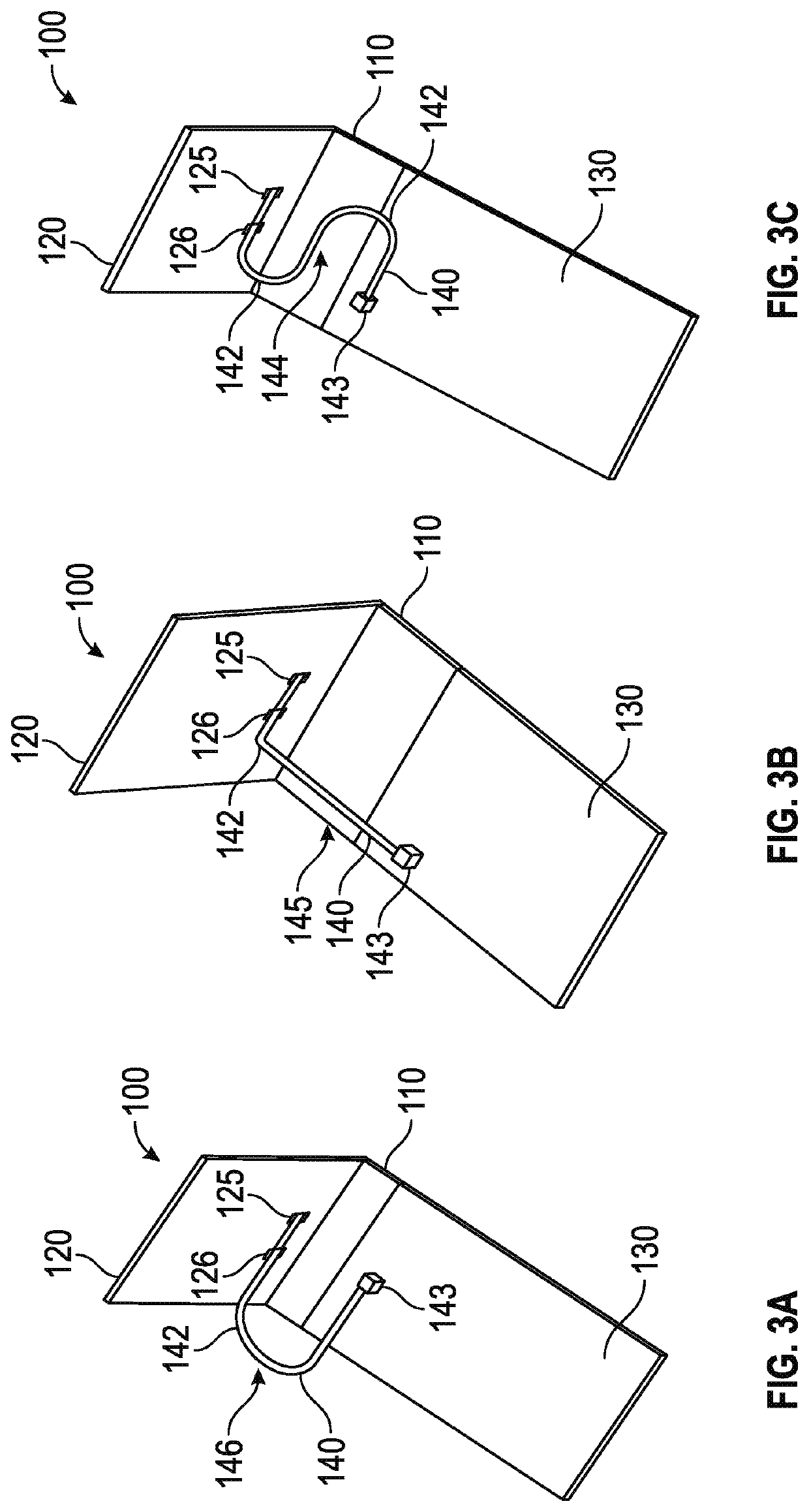
[0048]FIG. 1 shows a perspective view of an antenna system (100) in accordance with a first illustrated embodiment. The antenna system comprises a clearance zone (110) having a first end (111) and a second end (112). An antenna element (120) is coupled to the first end and comprises an antenna angle relative to the clearance zone. Coupled to the second end is a ground plane (130). The ground plane and clearance zone are generally coplanar such that they form a flat structure. Disposed on an antenna substrate (127) of the antenna element is a plurality of elements (122), a positive terminal pad (125) and a negative terminal pad (126). A short cable (140) is coupled to a top surface (131) of the ground plane and further coupled to the antenna element. The short cable comprises a short cable routing (141) having at least one bend (142). A shown, the short cable routing comprises an inverted C short cable routing (149). However, other short cable routings may also be utilized as disclos...
second illustrated embodiment
[0068]FIG. 6 shows a perspective view of a MIMO system (201) in accordance with a second illustrated embodiment. The MIMO system comprises a system substrate (260) having a perimeter (262) and a center portion (261) disposed therebetween. The perimeter comprises a clearance zone (210) and the center portion comprises a ground plane (230). Disposed on a substrate periphery (263) are a plurality of sides (264). As shown, each of the plurality of sides comprises a plurality of antenna systems (200), namely two. Each of the plurality of antenna systems couples to the MIMO system ground plane via a short cable (240) coupled to the ground plane and further coupled to each antenna element (220) of each of the plurality of antenna systems.
[0069]Each antenna element (220) is acting as both a resonator and absorber and will impact neighboring antenna elements and could affect performance. By utilizing various combinations of cable length and short cable routing, an extra level of tuning is ac...
third illustrated embodiment
[0070]FIG. 7 shows a perspective view of a development kit (301) in accordance with a third illustrated embodiment. The development kit comprises an antenna system (300) encapsulated within a plastic housing (360). The antenna system comprises an antenna element (320) electrically coupled to a ground plane (330) by a short cable (340) wherein the short cable comprises at least one bend (342). Disposed between the antenna element and ground plane and further disposed below the short cable is a nonconductive clearance zone (310). The short cable terminates at the ground plane by a ground terminal (343), the ground terminal being coupled to a transmission line (350) at a first terminal (351) of the transmission line. A second terminal (352) of the transmission line extends away from the clearance zone and the antenna element. The second terminal couples with a connector (353) for connecting to a radio. The connector is disposed on a bottom surface (332) of the ground plane. The plastic...
PUM
 Abstract
Description
Claims
Application Information
 - R&D
- Intellectual Property
- Life Sciences
- Materials
- Tech Scout
- Unparalleled Data Quality
- Higher Quality Content
- 60% Fewer Hallucinations
Browse by: Latest US Patents, China's latest patents, Technical Efficacy Thesaurus, Application Domain, Technology Topic, Popular Technical Reports.
© 2025 PatSnap. All rights reserved.Legal|Privacy policy|Modern Slavery Act Transparency Statement|Sitemap|About US| Contact US: help@patsnap.com


