Automatic blade changing system

a technology of automatic blade change and blade replacement, which is applied in the direction of metal-working machine components, metal working apparatus, manufacturing tools, etc., can solve the problems of manual blade replacement, high cost, and inability to automate the dicing operation

Inactive Publication Date: 2000-02-29
TOKYO SEIMITSU
View PDF7 Cites 55 Cited by
  • Summary
  • Abstract
  • Description
  • Claims
  • Application Information

AI Technical Summary

Problems solved by technology

Since it is difficult to automatically change blades, the replacement is currently performed manually.
As stated above, the manually-performed blade replacement is an obstacle to automation of the dicing operation as a whole.
The above-mentioned automatic blade changers, however, have a problem in that the structure is very complex, requires high costs, and the replacement is also complicated, since both of the blade attachment and detachment means and the nut attachment and detachment means have to be provided.
Japanese Utility Model

Method used


Image

  • Automatic blade changing system
  • Automatic blade changing system
  • Automatic blade changing system

Examples


Embodiment Construction

This invention will be described in further detail by way of example with reference to the accompanying drawings.

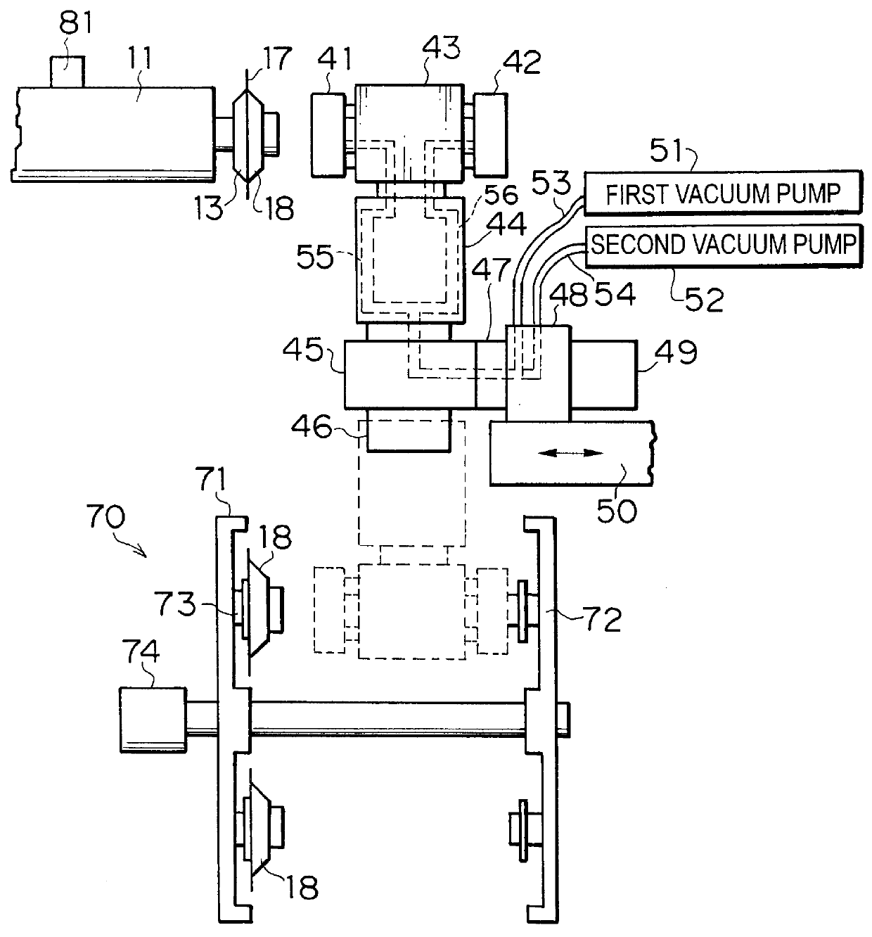
FIG. 2 shows the entire structure of an automatically blade exchanging system according to the present invention.

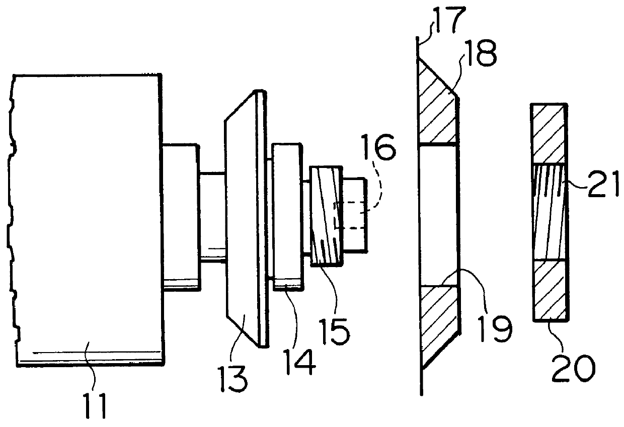
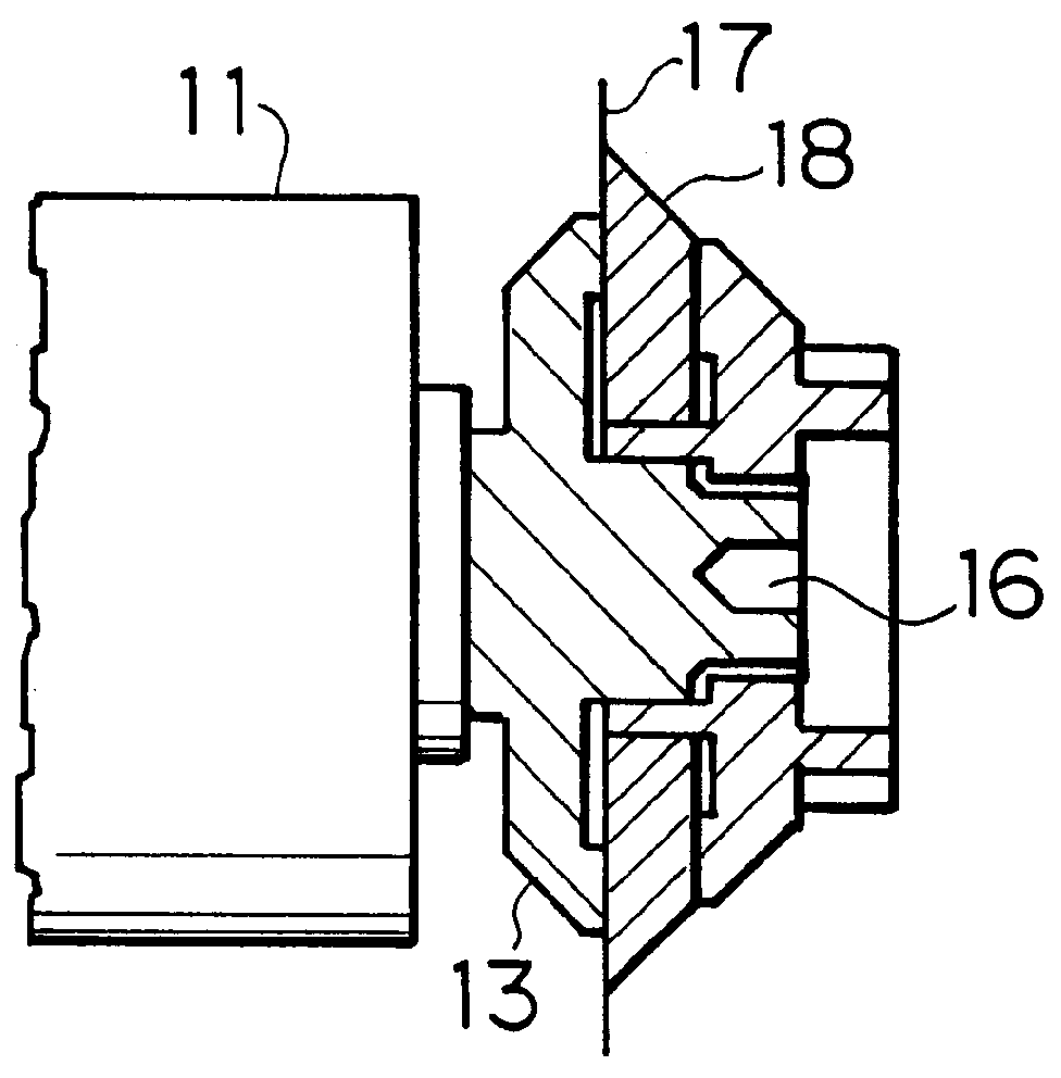
In FIG. 2, reference numeral 11 is a spindle, 13 is a support provided on a spindle shaft, 17 is a blade, 18 is a hub, 81 is a vibrometer which is provided on an outer periphery of the spindle 11. Reference numerals 41-56 indicate factors which construct a mechanism attaches and detaches the blade and a mechanism which moves the blade. Reference numeral 70 is a blade accommodating mechanism.

FIG. 3(A) shows a blade and an auxiliary stopper, and FIG. 3(B) shows a blade assembly constructed thereby. As shown in FIG. 3(A), the blade 17 is provided with the hub 18 in order to be attached to the spindle shaft, and the hub 18 is provided with an engaging part 19 and has the standard shape. The auxiliary stopper 31 consists of an engaging part 32 which is fitted into t...


PUM

PropertyMeasurementUnit
Speedaaaaaaaaaa
Circumferenceaaaaaaaaaa

Abstract

An automatic blade changing system of a dicing machine uses a blade which is fixed to an auxiliary stopper member provided with a thread which is engaged with a thread of a spindle. The automatic blade changing system consists of two blade holding means which hold the blade to which the stopper member is fixed and rotate the blade relatively to the spindle in the state wherein the blade is forced to the spindle, a blade accommodating means which accommodates a blade to replace the blade, a moving means for moving the blade holding means between the end of the spindle and the blade accommodating means.

Description

1. Field of the InventionThe present invention relates to an automatic blade changing system which automatically changes blades in a dicing machine which dices a semiconductor wafer, etc.2. Description of Related ArtThe dicing machine dices the semiconductor wafer by rotating, at high speed, a thin blade which is made of abrasive grains such as diamond strengthened by nickel, etc. FIG. 1 shows an example of a conventional blade attachment structure in the dicing machine. As shown in FIG. 1, a support 13, an engaging part 14, a thread 15, and a hexagon hole 16 for fixing a spindle 11 are provided at the end of the spindle 11. A blade 17 is fixed to a hub member 18, which is provided with an engaging part 19 which is engaged with the engaging part 14. The blade 17 is pressed in order to come into contact with the support 13 so that the engaging part 14 can be engaged with the engaging part 19. A thread 21 of a nut 20 is engaged with the thread 15. The blade 17 requires the good rotati...

Claims


Application Information

Patent Timeline
IPC IPC(8): B28D5/00B28D5/02B27B5/00B27B5/30B27B5/32
CPCB27B5/30B27B5/32B28D5/0058B28D5/022Y10T483/1733Y10T483/1736Y10T483/1755B23Q3/15766Y10T83/9379B23Q3/15539B23Q3/15722B23Q2003/155418B23Q2003/155428B23Q2003/155439
Inventor AZUMA, MASAYUKIADACHI, TADASHI
Owner TOKYO SEIMITSU
Why Eureka
Try Eureka