Flooring system

Inactive Publication Date: 2000-03-07
GULIOTTI ASSOC
View PDF21 Cites 51 Cited by
  • Summary
  • Abstract
  • Description
  • Claims
  • Application Information

AI Technical Summary

Benefits of technology

Another object of the present invention is to provide a flooring system which is readily adaptable as an athletic floor, particularly for use over ice.
A still further object of the present invention is to provide a fl

Problems solved by technology

The flooring systems noted above still lack means to facilitate a tight abutting edge-to-edge

Method used


Image

  • Flooring system
  • Flooring system
  • Flooring system

Examples


Embodiment Construction

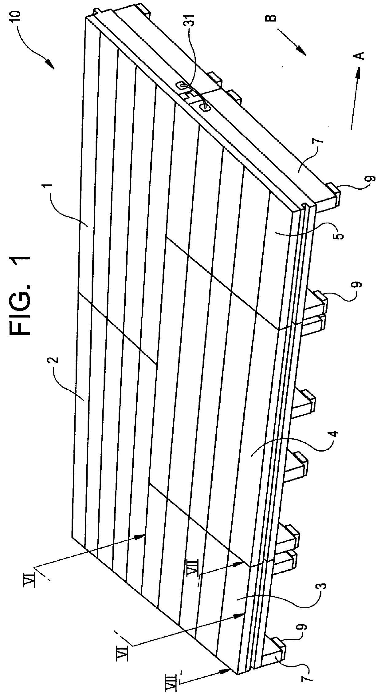
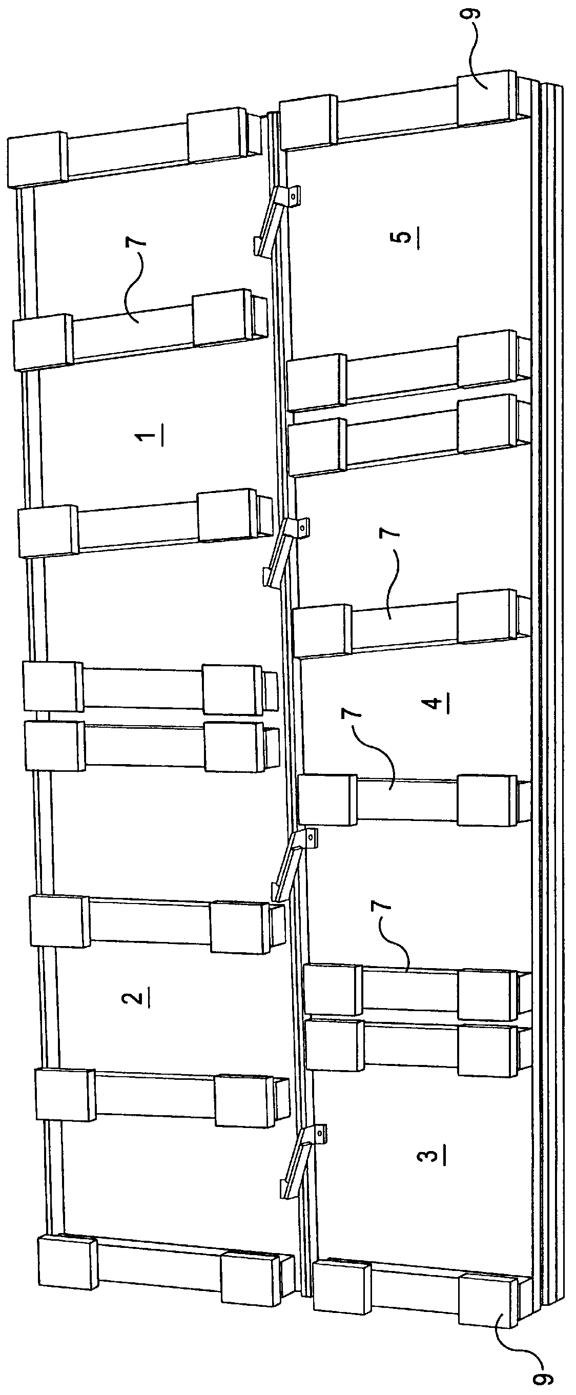
One embodiment of the invention flooring system is designated by the reference numeral 10 in FIGS. 1 and 2 and is seen to depict floor sections, 1, 2, 3, 4 and 5. Sections 1, 2 and 4 are elongated rectangular sections with sections 3 and 5 being square. For description purposes, the arrow A shown in FIG. 1 designates the longitudinal direction with Arrow B being the transverse direction. The sections 1, 2 and 4 are arranged in a staggered relationship to each other. The square sections 3 and 5 are used as end fillers in the assembly where necessary. It should be understood that more than two of the elongated panels could be linked longitudinally. In addition, more than one set of the sections 1-5 could be linked transversely.

The sections are supported by spaced apart floor joists 7, the floor joists 7 including, if desired, resilient pads 9.

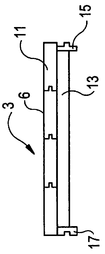
The sections 1-5, are equipped with tongue and groove construction in the longitudinal direction and, where appropriate, in the transverse direc...


PUM


Abstract

A portable floor system has a plurality of modular floor sections each formed by floorboards and a subfloor for support and each having either a tongue or a groove at its periphery. A plurality of spaced-apart floor joists extend downwardly from the subfloor. The tongues and grooves are matingly arranged. Mounted to the undersurface of each floor section are one or more wedging clips configured to cooperate with a clip of an adjacent section to interconnect adjacent floor sections.

Description

The present invention is directed to a flooring system and, in particular, an athletic flooring system employing a plurality of flooring sections, each of which utilizes wedging clips for secure longitudinal section attachment.In the prior art, various types of modular flooring systems have been proposed. U.S. Pat. No. 2,635,450 to Orzel discloses a slab construction for buildings. L-shaped side lugs extend from slab side faces of flooring slabs for interlocking with adjacent flooring slabs.Other flooring construction uses metal clips as shown in U.S. Pat. No. 1,710,610 to Duke. Tongue and groove construction is shown in U.S. Pat. Nos. 2,019,692 and 2,102,806 to Mueller. U.S. Pat. No. 2,834,065 to Mueller also utilizes anchor plates or clips around a dance floor periphery.The flooring systems noted above still lack means to facilitate a tight abutting edge-to-edge engagement when floor panels are moved length-wise relative to each other and into assembly. Consequently, a need has de...

Claims


Application Information

Patent Timeline
IPC IPC(8): E04F15/04
CPCE04F15/04E04F15/02E04F2201/0123Y10T403/635E04F2201/05Y10T403/64E04F2201/021F16B2200/50
Inventor GUGLIOTTI, JAMES M.GUGLIOTTI, DAVID P.
Owner GULIOTTI ASSOC
Why Eureka
Try Eureka