Multilayer capacitor

a multi-layer capacitor and capacitor technology, applied in the direction of capacitors, fixed capacitor details, fixed capacitors, etc., can solve the problems of insufficient reduction of esl and insufficient improvement of high frequency performan

Inactive Publication Date: 2000-03-07
MURATA MFG CO LTD
View PDF4 Cites 153 Cited by
  • Summary
  • Abstract
  • Description
  • Claims
  • Application Information

AI Technical Summary

Problems solved by technology

Thus, the ESL is not sufficiently reduced and high

Method used


Image

  • Multilayer capacitor
  • Multilayer capacitor
  • Multilayer capacitor

Examples


Embodiment Construction

590 Comparative Example 2 73 ______________________________________

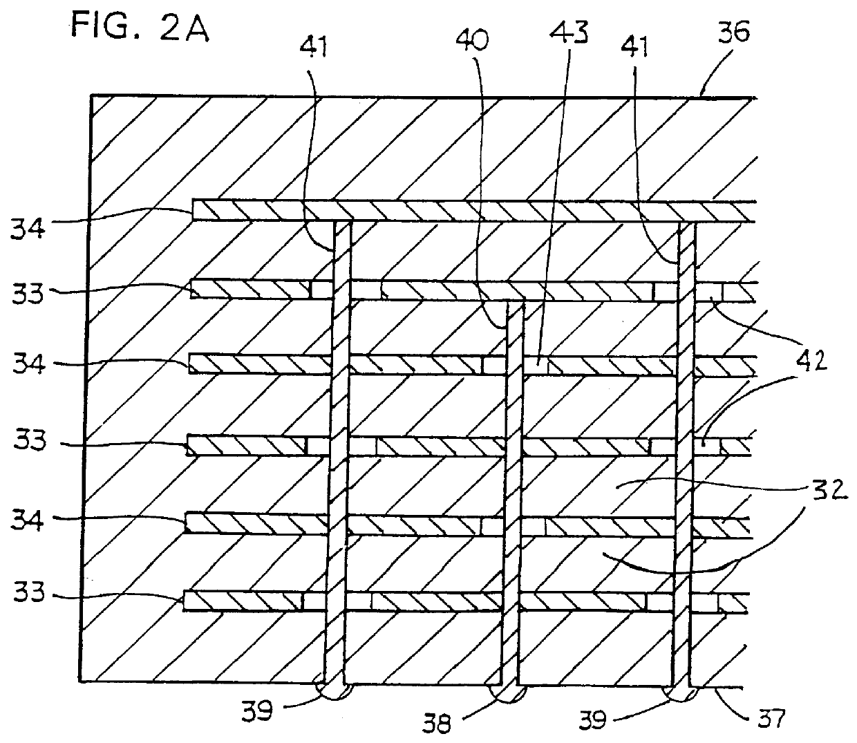
It is apparent from Table 1 that the ESL was reduced more effectively with the structure of the present embodiment than with the structure of either of the comparative examples 1 or 2. While it is apparent that the components of magnetic flux induced by currents flowing through the internal electrodes of the comparative example 2 was canceled more efficiently than in the comparative example 1, it will be understood that it had a high self-inductance compared to the present embodiment. This is because the currents in comparative example 2 flow through the first and second connection portions in the same direction. Conversely, the currents in the present embodiment flow through the first and second connection portions in opposite directions.

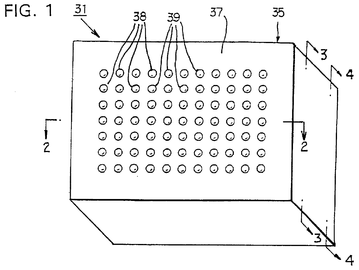
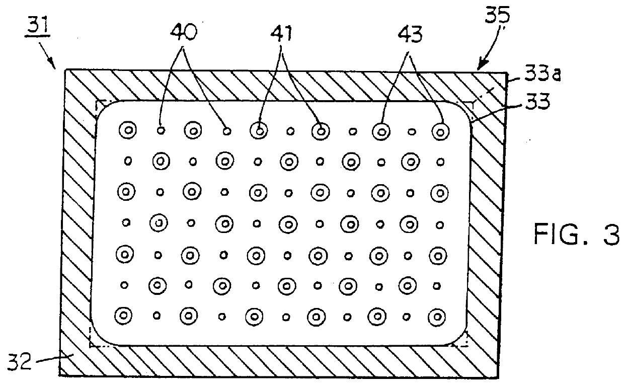
To determine the best arrangement of the connection portions 40, 41 of the present invention, additional tests were conducted. In each of the test samples, a multilayer capacitor 31...


PUM


Abstract

First and second external terminal electrodes are formed on the same principal surface of a capacitor main body. The connection between first internal electrodes in the capacitor main body, the first external terminal electrode and the mutual connection between the plurality of first internal electrodes is achieved by a first connection portion. The connection between second internal electrodes, the second external terminal electrode and the mutual connection between the plurality of second internal electrodes is achieved by a second connection portion. The first and second connection portions are arranged alternately. Currents flow through the connection portions in opposite directions with the result that components of magnetic flux generated by such currents are cancelled and the ESL is reduced.

Description

1. Field of the InventionThe present invention relates to a multilayer capacitor and, more particularly, to a multilayer capacitor which can be advantageously used in high frequency circuits.2. Description of the Related ArtFIG. 7 shows a schematic sectional view of a typical prior art multilayer capacitor 1 which includes a main body 5 having a plurality of ceramic dielectric material layers 2 stacked one on top of the other. A set of first internal electrodes 3 and a set of second internal electrodes 4 are arranged alternately, with a respective dielectric material layer 2 located between adjacent pairs of electrodes 3 and 4 to form a plurality of capacitor units.Each of the first internal electrodes 3 is electrically coupled to a first external terminal electrode 8 formed on a first end face 6 of the main body 5. Each of the second internal electrodes 4 is electrically coupled to a second external electrode 9 formed on a second end surface 7 of main body 5. As a result, the elect...

Claims


Application Information

Patent Timeline
IPC IPC(8): H01G4/30
CPCH01G4/30
Inventor NAITO, YASUYUKITANIGUCHI, MASAAKIKURODA, YOICHIKONDO, TAKANORI
Owner MURATA MFG CO LTD
Why Eureka
Try Eureka